


Desktop Companion Bot (DCB) V0.1
It's been a while since I submitted a robot. Now here he goes, the Desktop Companion Bot or short DCB.
Prolog:
The idea came by thinking about a new swarm robot. For the first testing I wanted to build a dektop robot to test the wireless charging function. It has to be a simple robot, small, cheap and easy to build.
Parts:
The parts are nothing fancy as you can see in the following pictures.
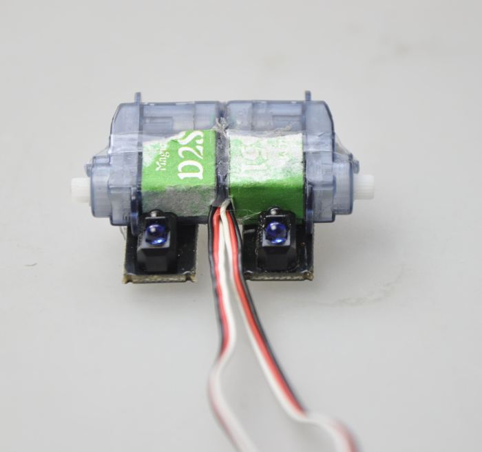
Two continuous rotating servos 2.5g hotglued together.
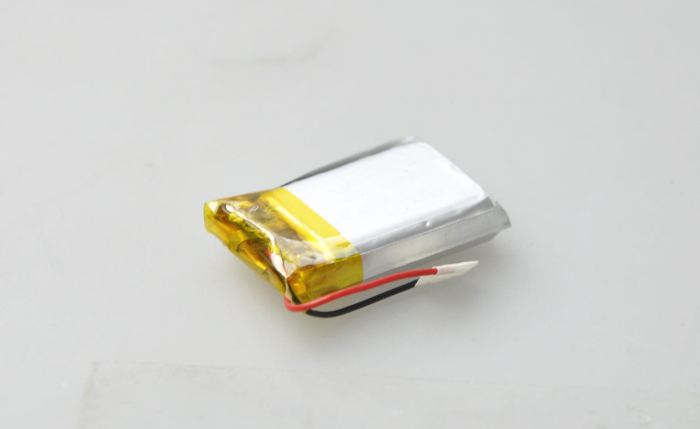
One LiPo 3.7V 500mAh
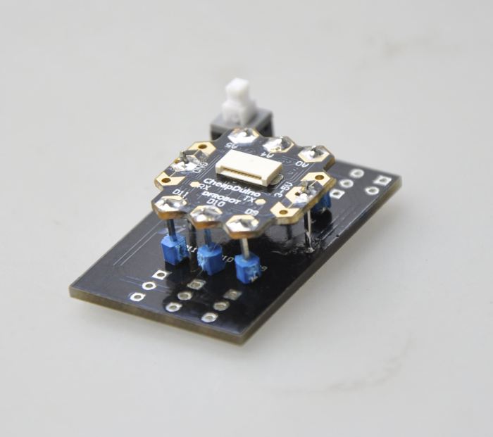
One Cheapduino, already soldered on the shield.
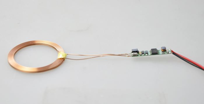
One wireless charging circuit. (receiver part is regulated to 5V)
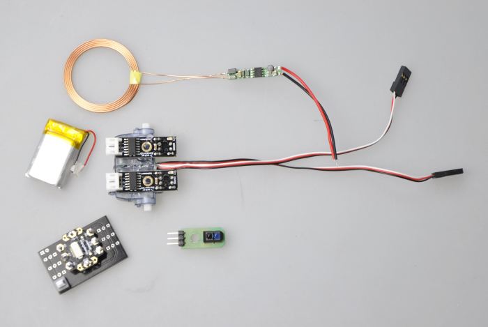
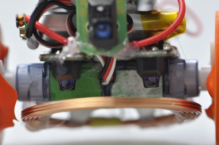
Here is the most of the parts in one picture. In the center you can see the two IR sensors already hotglued on the servos. These are based on TCRT5000 and will act as line and cliff sensor. The third IR sensor is another TCRT5000 and will serve as front sensor (common obstacle avoidance).
As it's for testing the wireless charging function and some programming only it's just hotglued together. The following pictures will show the first steps in putting all together. First fixed with Blu Tack and later with the more permanent hotglue :-)
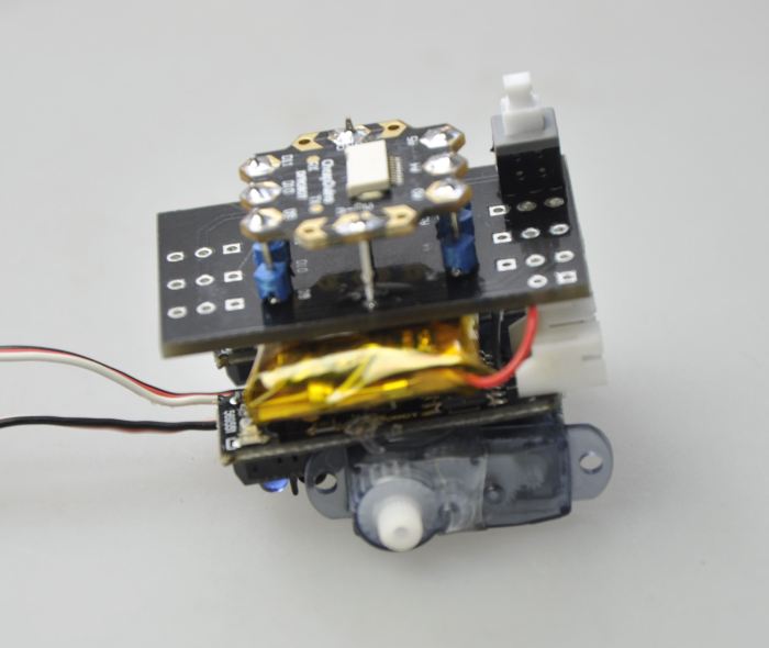
The IR line/cliff sensors are hotglued on the servos. On top of it is the LiPo battery and on top of that is the Cheapduino shield including the Cheapduino..
Then the wireless charging circuit is attached with Blu Tack at the side of the LiPo battrery and the coil at the bottom.
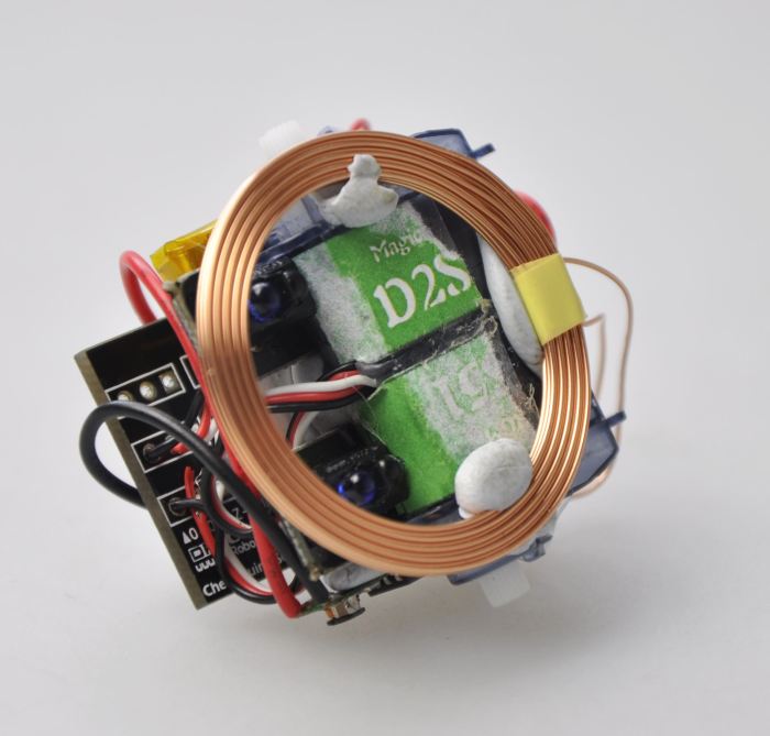
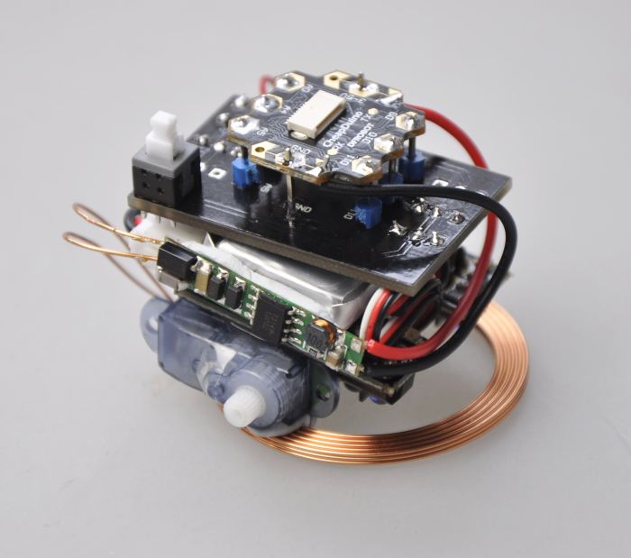
The coil is still fixed with Blu Tack here...
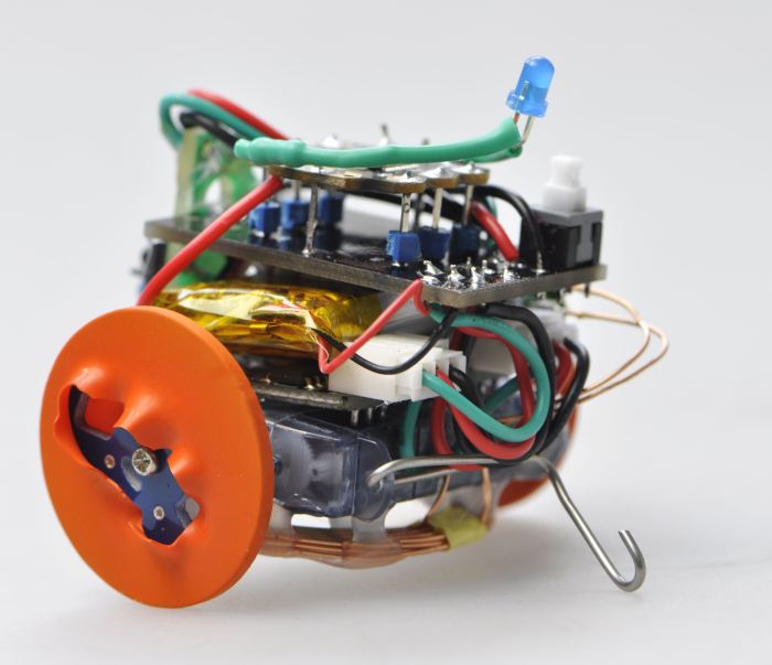
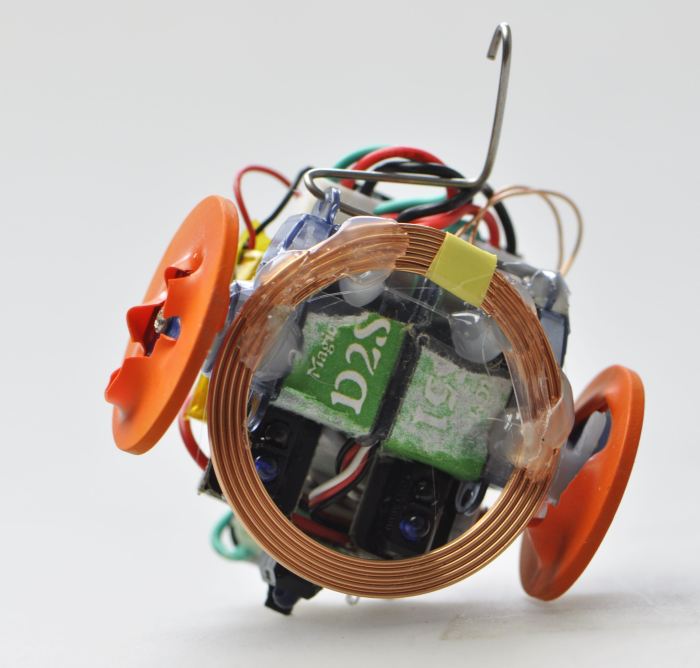
All wired up and attached two wheels from the new ALF. The balloon rubber thing is for grip...not looking very nice but that's what I had at my hands right now. In the back the steel wire is keeping DCB in balance.
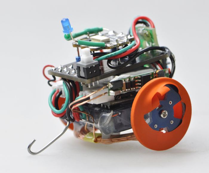
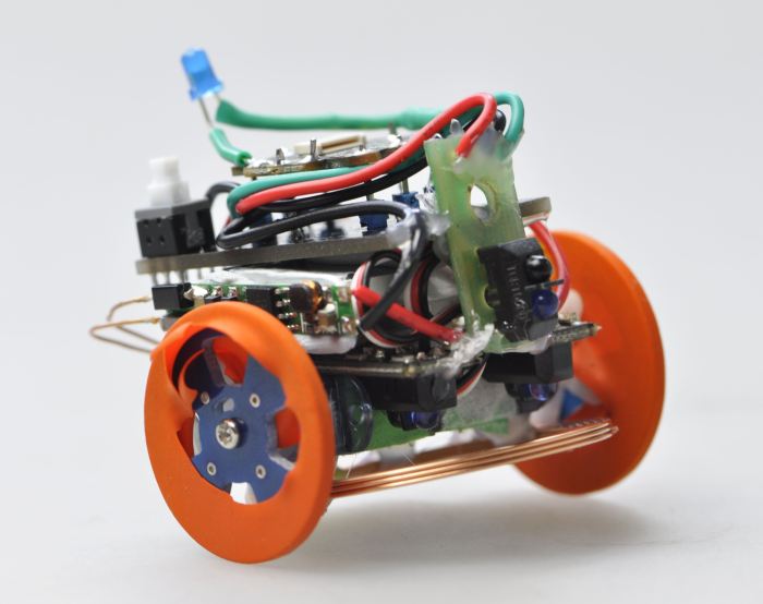
More pictures without comment:
There is no video yet. The plan is to write some code today and then I will upload some motion pictures :-) Also the plan is to let it run on a contained area with an webcam watching it 24/7. If that happens I will post the link here as well.
Here some data of the wireless charging circuit taken with the sender and receiver coil 10mm apart:
| Input/V | Primary current/mA | Output/V | Secondary current/mA |
| 3.00 | 200 | 0.30 | 55 |
| 3.50 | 170 | 0.30 | 55 |
| 4.50 | 144 | 0.40 | 55 |
| 5.00 | 160 | 1.80 | 66 |
| 6.00 | 170 | 2.70 | 73 |
| 8.00 | 200 | 4.40 | 89 |
| 10.00 | 200 | 4.50 | 92 |
| 12.00 | 197 | 4.60 | 94 |
The coils are made of 15 windings (5 in 3 layers) solid 0.25mm² copper wire and haveinf a diameter of 40mm.
The primary coil is running with 50kHz provides by the T5336 chip (might be a Chinese one)
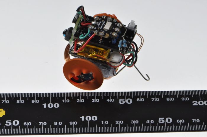
As on a request of Maxhires here some pictures to show you the size of the robot:
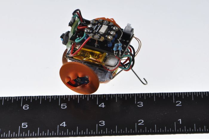
Above is the DCB in relation to a ruler in INCH (for all of you who still lifes in the antique imperial system)
below you can see the robot in relation to the modern metric system \o/
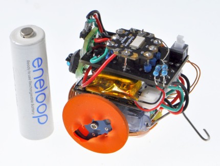
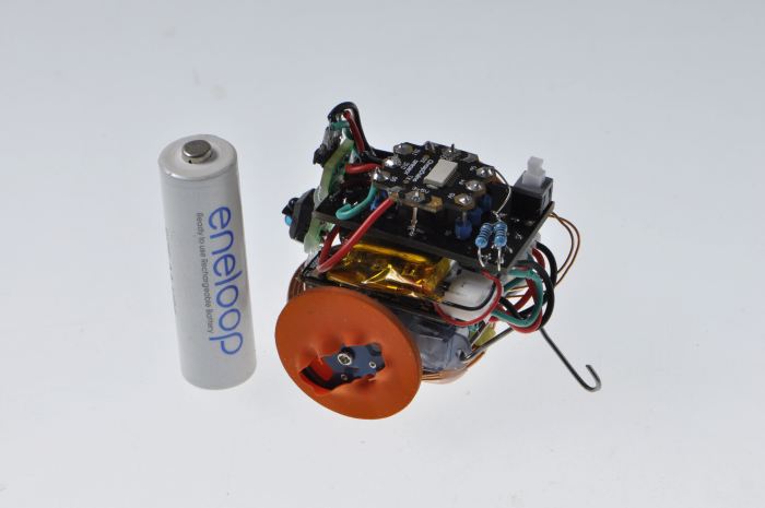
For all of you who needs a physical thing to compare, please see the next picture with the robot besides a standard AA battery.
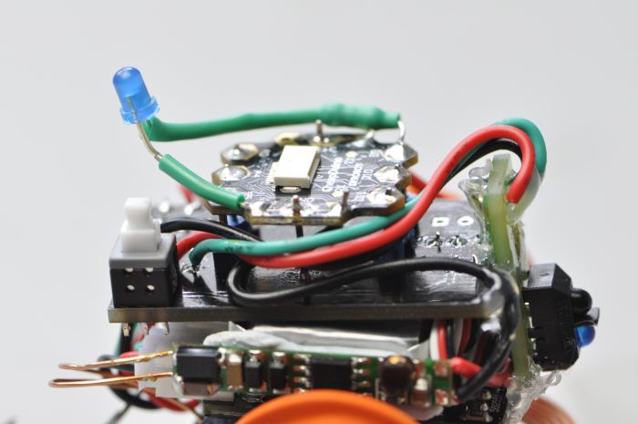
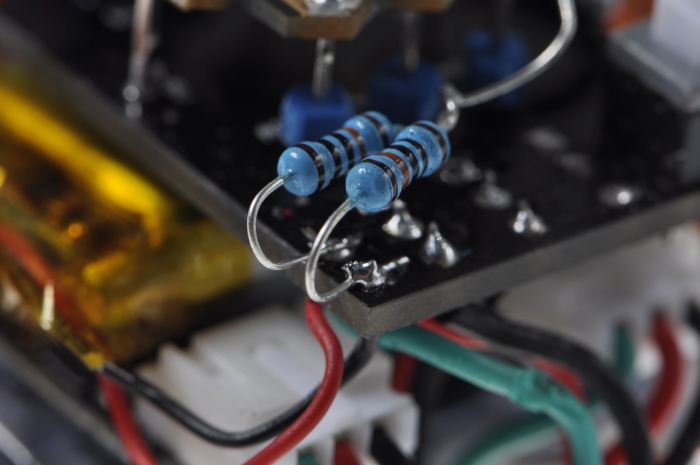
The next picture is showing the two resistors (each 100kΩ) of the battery monitor.
Today is coding and testing day. I will write the code to navigate the robot in the right position above the primary coil to charge the battery most efficient. For that I also need to test run the robot in his contained area. Not sure about the result yet since it's a whole bunch of parameters to take care of.
UPDATE: Completed. The little huy got disassambled since one servo was broken. I will build a new one soon but this will be another project. However, I've learned a lot, so it was a success.
UPDATE: As requested here are the link to the schematics of the Cheapduino.
Moving in a contained area, avoiding obstacles, checking battery power, find a line, find a cliff
- Actuators / output devices: 2x 2.5g continuous rotating servo, 1x blue 3mm LED
- Control method: Autonomous with Cheapduino
- CPU: atMega8
- Operating system: Arduino IDE
- Power source: 1x 3.7V LiPo 500mAh
- Programming language: Arduino ide
- Sensors / input devices: 3x IR sensor TCRT5000, Wireless charging coil
- Target environment: indoor, Flat, Even surface