


Deacon (Code name A1B1)
INTRO
This project -christened Deacon- is the next step in evolution from Nigel, who was abandoned last year.
June 9th, 2011
As it was recently settled on a forum post, the H-Bridge design I´ll implement (after I make it) is one borrowed from Pyro Electro Tutorials. http://www.pyroelectro.com/tutorials/h_bridge_4_transistor/index.html. I do have one L293D IC in stock, but I believe building the one in the link will be a nice learning experience.
(NOTE: I have desisted from building Pyro Electro´s H-Bridge design due to a flaw that Dan M brought to my attention. For more info on this and for a better design, see the comments below)
The goal in this first stage is to remotely control it, having it move forward, backward and turn at different speeds via PWM. Once that is done, I´ll get more ambitious. For now, I am taking a "one step at a time" approach so that this project doesn´t engulf me and spit me out (as it had in the past).
June 17th, 2011
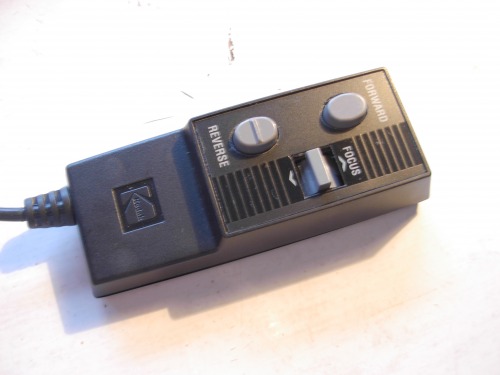
For lack of a couple of components (amateur mistake) and trapped in a long weekend, I had to postpone the build of Pyro´s H-Bridge, but decided to move forward with the L293D I had purchased. That IC in a protoboard, stars in the film located towards the top of this page, with a brilliant supporting performance by a hacked Kodak Ektagraphic projector remote control.
June 21st, 2011 (First day of Winter):
Happy to report that STAGE 1 is now complete. The platform is functioning. I decided against using PWM at this stage. So basically what I have is a functioning remote control tank.
I have decided that the next Stage is to add line-following capabilities to the platform, and since what is finally driving the motors is a L293D, I´ve decided to go with this tutorial: http://www.societyofrobots.com/member_tutorials/node/62. Even though I have a bunch of Picaxes lying around that are anxious to see some action, I thought I´d keep it simple.
June 25th, 2011 (Fourth day of Winter):
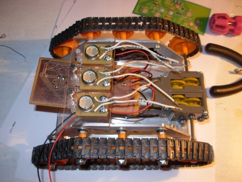
Happy to report that STAGE 2 is well under way. I have devised and built a standalone module that just needs a power input (>6 VDC) and has a connector that outputs voltages for 3 different LDRs. Each reads light from it own LED. I have slept on it, and instead of going with the tutorial from Society of Robots, I´ll control everything with a Picaxe 18X.
This module will sit in the guts of the robot, while the Picaxe 18 Protoboard (that I still need to improvise) while sit on top of the permanent standoffs that I have placed on top of it.
June 30th, 2011 (Tenth Day of Winter)
One of the mistakes I never get tired of making is jumping to making my own boards before I fully test a circuit in a breadboard. And I´ve done it again. On the 25th, I commited my design to a PCB and ever since then I have been reviewing and modifying it ad nauseam. There are 3 particular resistors whose values I have changed a number of times, trying to get the voltage divider with the CdS cells to work the way I want it to. Rookie mistake. It is just that my OCD will not let me enjoy a temporary circuit... they are just sooooo messy! It is very frustrating when wires come loose... (Note to self: maybe it´s time to invest in those fancy cables for the breadboard, instead of using these bits of wire cut to length...)
Anyway, back to the point. Little progress was made these past 5 days, other than tinkering with the line follower module, getting it to work just right.
July 2nd, 2011 (Twelth Day of Winter)
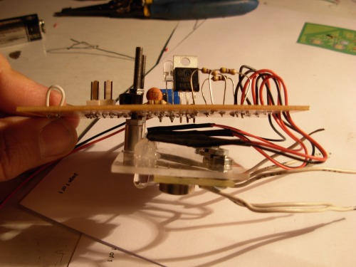
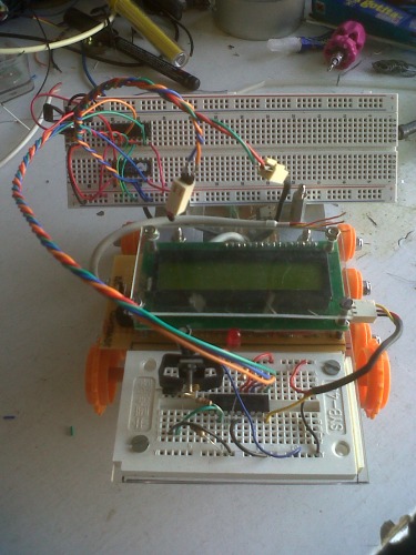
The line follower board is finally ready. It is also properly mounted to the chassis. Take a look:
Next step is to start playing around with code. Little experience in this department, so I don´t expect progress to be mindbogglingly fast. For the time being, I have placed my DIY Picaxe 08M Protoboard on top of the chassis so as to start experimenting with intercommunication between both boards. Once I get a feel for the average values produced by the follower board on the ADC pins of the 08M, I´ll remove the protoboard and start working on the DIY 18X protoboard.
July 6th, 2011 (Sixteenth Day of Winter)
Very frustrated here!
All my Picaxe 08M protoboard+L293D on a breadboard+my line follower board experiments were a disaster. So far, I didn´t get a single thing to work right. For troubleshooting sake, I have broken everything up into 3 boards trying to locate specific problems. Everything is a mess. I am concentrating on the L293D. But I am using the Tamiya Twin Gearbox and those Mabuchi motors only use 3VDC, and for some reason; I can´t get them to work. I don´t know if the 4,5 VDC minimum voltage specified in the datasheet also applies to pin 8, which is the motor VCC. If that is not the case, then I don´t know why (the hell) this thing is not working!
Very frustrated here!
July 13th, 2011 (23rd Day of Winter)
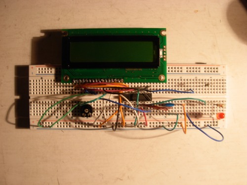
Just as I was ready to set the entire project ablaze, both my mail orders arrived. The FRM010 Serial Firmware IC from Picaxe (to control a LCD Display with just one output pin) and both Sharp IR Sensors. That peaked my interest, so I decided to take a break from troubleshooting the line follower portion of the project. Trying to get the FRM010 and my Winstar LCD to talk to each other recquired an abrupt learning curve, that has been properly documented here: http://www.picaxeforum.co.uk/showthread.php?t=15150.
I took a page out of my own book and experimented with the circuit as much as I needed on the breadboard stage. Once that was fully tested, I moved on to a more permanent solution.
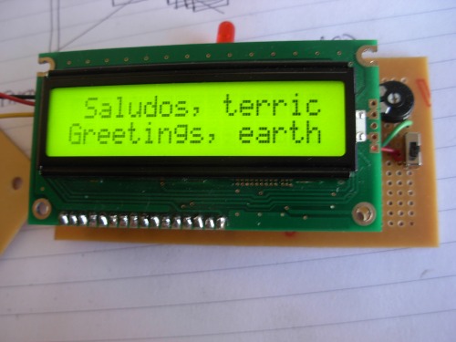
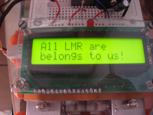
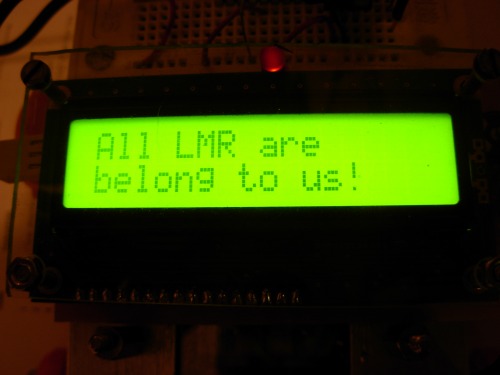
I thought it would be cool to have the following welcome message every time I switch it on: "Greetings, earthlings!" or, if you prefer, "¡Saludos, terrícolas!" in my native Spanish. On the right hand side of the display, on the bottom board, what you see are the pot for the contrast of the characters and I included a small switch for the backlight, to cut down on current consumption when powered by batteries and not needed.
I haven´t even touched the Sharp sensors because of the stubborn JST connector that they come with. It has probed to be almost impossible to get locally. Had I known about these, I would have ordered them together with the sensors. I am not about to place another order just for those. Worst comes to worst, I´ll desoder them and put something else in its place.
July 15th, 2011 (25th day of Winter)
Some more progress!
The line follower board is finally working at 100% capacity. Not only that, but it is even talking to the LCD. I have jolted down an easy routine to monitor in real time the 3 ADC values generated by the 3 sets of LED+LDRs. Then I even added a line to state below which LDR the black line is located.
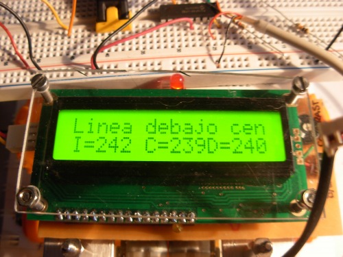
First line: "Linea debajo cen" means Line below center (LDR). Second line: real time monitoring of the 3 LDRs: I=Left, C=Center and D=Right, -also in Spanish-.
Next in store is: using the same routine to control an L293D. Shouldn´t be that hard.
July 22nd, 2011 (31st day of Winter)
I hve added the drawing of the chassis of my base to the download list. In case anyone cares to look at it closer.
July 25th, 2011 (34th day of Winter)
That´s more like it!
August 1st, 2011 (41st day of winter)
Well, after a rather frustrating experimentation period with PIC-AIM, my break from Deacon is over. I am still trying to figure out stupid little details like the interaction of the L293D and the Tamiya Twin Gearbox Motor. The MIN voltage accepted by the IC is 4.5VDC and that seems to be too much for the motors. I am feeding it 5VDC and the IC is dropping very little tension so I will add some passive components to get it closer to the 3.0VDC that it likes. I have added the motor datasheet to the download list for reference.
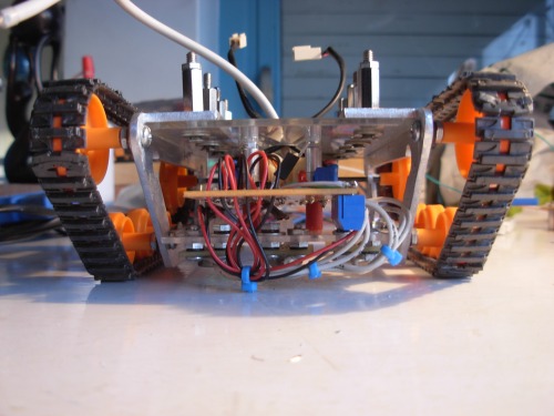
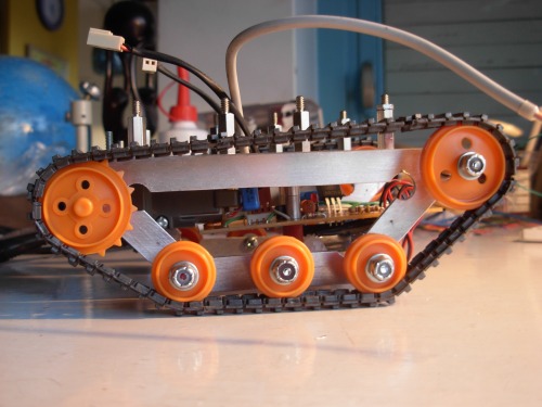
BTW, If anyone was wondering, let me tell you why there are so many pictures of Deacon with the treads off. It is a comfortable way of testing code. Since the drive wheel is up in the air, if I remove the treads I can try out different speeds and directions without the thing actually moving. Very handy.
August 5th, 2011 (44th day of Winter)
I have added a third video. This is the first showing autonomous movement. (Yay). This first example is a very crude piece of code that has the thing move forward for 5 seconds. Stop for 5 seconds. Move backwards for 5 seconds and stop again for another 5 seconds. Then it cycles again... ad eternum (which is latin for "as long as the batteries last"). This weekend I´ll commit the circuit in the bigger protoboard (v 2.0 not v 1.5 in the picture above) to a permanent board so that I can experiments with new aspects, such as PWM the enable pin of the L293D, or first attempts at line following.
August 6th, 2011 (45th day of Winter)
The circuit mentioned above has already found a permanent residence in a homebrew board.
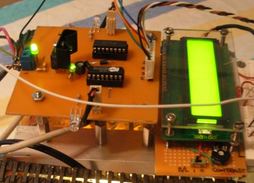
I am happy to report that it worked fine from the first try (which is a first). Trying out different pieces of code is now comfortable (as opposed to messy) and that makes me happy. I have toyed around with it and had the best afternoon.
Last step is to connect the output of the line follower board to the inputs of the Picaxe 18X that still finds shelter in a protoboard. That, and fiddling with the line follower code. This project is nearing completion!
August 10th, 2011 (49th day of Winter)
Last night I started experimenting line following with a very crude code. You can find it in the attachments list. Criticism and pointers welcome.
August 17th, 2011 (56th day of Winter)
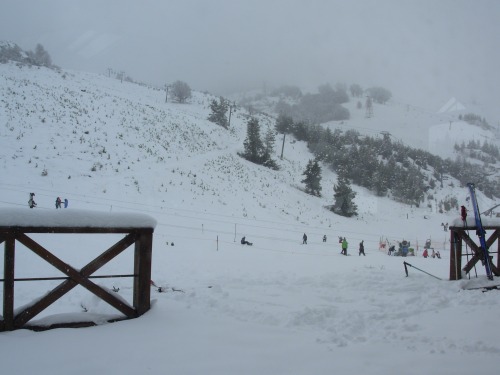
The wife skis. I never tried. We will stay here until Sunday. I took snowboarding lessons the other day. The teacher was an absolute dick. I am in much pain since then. I will have to take it up. Until then, this is my view.
August 23rd, 2011 (62nd Day of Winter)
First of all, I´m back. Missed me? :(
Now, I´ve been experimenting with some different approaches to the line following code. It is working, but not accurately enough. I´ve been thinking about the core principles of the system, and I´ve come to doubt the philosophy behind it. As it stands right now (see code snippet below), I am storing ADC values into variables and then comparing them.
readadc 0,ADC_CEN ;Read pin voltage of 3 LDRs into ADC
readadc 1,ADC_LEF
readadc 2,ADC_RIGlet CMPNS8_CEN=255-ADC_CEN ;variables CMPNS8_CEN, LEF and RIG hold the difference between full 255 value and
let CMPNS8_LEF=255-ADC_LEF ;maximum LDR value taken over white
let CMPNS8_RIG=255-ADC_RIG
let CEN_LDR=ADC_CEN+CMPNS8_CEN max 255 ; variables CEN, LEF and RIG_LDR hold compensated value of light readings
let LEF_LDR=ADC_LEF+CMPNS8_LEF max 255
let RIG_LDR=ADC_RIG+CMPNS8_RIG max 255
...but, wouldn´t I be better off interpreting the output of the LDR as 1-bit digital? 0 for "over-line" and 1 for "over-white"? Do I really need 255 shades of gray? Does the code really need to be this complicated? 3 sets of 3 variables each to read the output of 3 LDRs? Overkill?
What got me thinking about this, is the book I read over the holidays: "The Robot Builder´s Cookbook" by Owen Bishop. It is nothing too fancy or complicated, but highly recomended for those of us who don´t have an enginnering degree. In said book, Mr. Bishop gives a recipe por turning the output of an analogue sensor (like an LDR) into a digital one using a comparator IC (a CA3140E to be precise).
So, borrowing a page from his book, why don´t I just build a no-nonsense truth table for the 3 LDRs? The only complication there would be the fine tuning of the reference voltage...
Does anyone have an opinion?
September 20th, 2011 (LAST day of Winter)
I didn´t want to miss out on posting something today, the very last day of winter in the bottom half of the earth. I guess a little recap is in order:
After Ignoblegnome´s response to my last post, I decided to follow the path he suggested: Keeping the line follower board as it was and incorporating a crude type of ADC in my code. And so I did. Now, if the value of certain LDR is above (let´s say) 185, the code interprets that as a logic high. If not, it´s a logic low.
This worked fine. It probed the point that 256 shades of gray are overkill for line following. 1 digital bit is all you need.
The last development was redoing the line follower board, but instead of the LDRs I was using, incorporating some sort of reflective optocoupler that are so fashionable now-a-days. I couldn´t find the QRD1114 or CNY70 locally, so I modified the concept for the only sensor I could find: the TLP907. I have already etched the board and I´ll try to put it together tonight.
October 16th, 2011 (26th day of Spring)
I haven´t updated this blog in a while, so I´ll bring you up to speed. After 5 or 6 versions of the the new line follower board (the one that incorporates the TLP907 sensor) I gave up on it. Two major problems: 1) the legs of the IC are too damned fragile. I kept breaking them and buying new ones. 2) The sensing distance is too narrow: less than 1.5mm off the face of it. I couldn´t align all 5 sensors so that all of them were less than 1.5mm off the ground.
I decided to orden QRD1114s from abroad and move on. (They haven´t arrived yet)
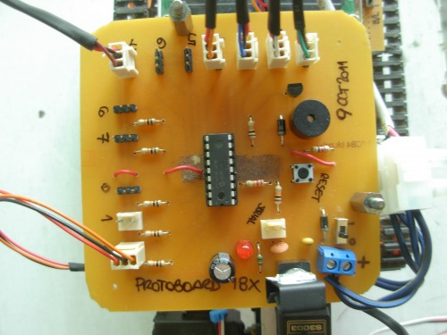
Next on my TO-DO list was come up with a protoboard for the PICAXE 18X. Happy to report that that is done and I´m currenlty testing it. You can take a look at it below.
I took advantage of this break from the line follower board to incorporate into Deacon the design I came up with here, in the last video uploaded. It´s your average pan/tilt arrangement but used differently. The idea is: when the bot is moving, the sensor will be pointing down to detect sudden drops. At regular intervals, the bot will stop and look up. It´ll pan 100° and determine the path with least obstacles. It will correct it´s course, look down and start moving again. This is what I´ve been up to. I leave you with some new pictures of Deacon.
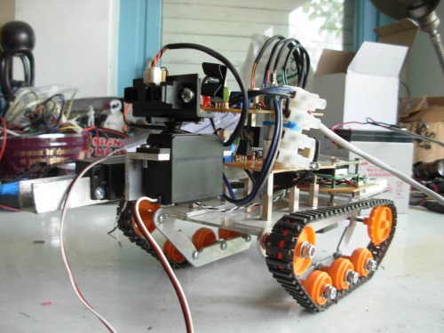
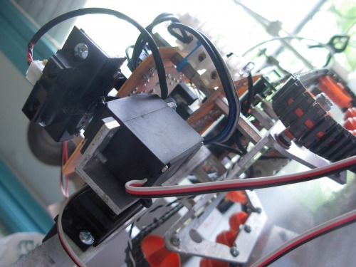
Phase one: Line Follower complete. Right now it is "learning" how to avoid obstacles the contact-free version.
- Actuators / output devices: Tamiya Twin Motor Gearbox, Winstar LCD
- Control method: Autonomous.
- CPU: picaxe 18x
- Programming language: Picaxe basic
- Sensors / input devices: LDRs, Sharp GP2Y0A21YK0F IR sensor
- Target environment: indoors