


Cyclops
Update 30/12/2012 V2
Great success! As described at the top of V8 of Cyclops on Paste bin:
Servo Sweep and Blind Spot checks are on seperate tabs, not included in the PB, but i figure those have been repasted tooo many times.
Update 30/12/2012
I have eliminated the delays, but how i arrange the desired programing into the code is a new problem.
Not helped by my not brilliant grasp of programming basics. What does which bit when? I think there is a gap in between starting the motors, and releasing the motors, during the movement. This would be the place to put it i guess?....
Hmmmm...
Update 17/12/12
Back again. I ordered some new M-F jumpers off ebay, so can now utilise a few more inputs. Modded my "line follower" array, to fit better on the front of the bot, so will be using the same part for "edge detection". Due to this though, i need to remove all my movement delays, and replace them with actual timing, I understand the delays stop the arduino from doing anything else, so it could drive off the edge of the table!
Update 04/12/2012
I mapped the vertical axis, to the time delay between running the motors, and stopping the motors, while moving forwards in a straight line. If the light is outside of the "forwards" window (which i made more generous) it spins towards the light, for a delay time defined by the angle on the horizontal axis.
Before it moves anywhere, it "checks to the rear", which involves, pointing the horizontal axis straight forward, and then flipping the veritcal axis between 30 degrees to the rear, and forwards. If the light is greatest behind, it spins 180, if not it doesnt. I was going to measure the angle to the rear, but it didnt add any advantage, and the put the servo wires under a bit of unessecary stress.
Unfortunatly, this update makes for some pretty boring robotic action! It either spins, 180, or doesnt. Then turns approximately to the light, then drives to it, in about "70% of the required distance" chunks to allow for a few adjustments on the way. Once there it sits and stops (delay of 99999999, because i am lazy.)
Thanks to OddBot, i have split my code into tabs to:
- The main control tab, with definitions, setup, and loop.
- Blindspot check (to the rear)
- Angle measurements
- Decisions
Due to this, i wonder if i can copy and paste.....doesnt look like it, not easily. I will look into it!
Update: 29/11/2012
So i applied the same code, to the vertical servo. i had to make a little adjustment to the servo mounting, so stop the vertical servo from clashing with the body when in took a reading to the rightmost extreme angle. I was initially going to write a complicated constraint, which constrained the vertical value, based on the hoizontal position, but realised it would be a hinderence later on, and the problem would easily be solved by moving the vertical servo onto a slightly longer servo arm, so it sat further away from the pcbs by about 10 mm.
I have been trying to work out how to get angles off my motors. the easiest way would be to buy a pair of encoders! i did have an old ball type mouse, which i took the encoders out of, but in trying to get them work, fried the IR sensor (oops). The other option is to do it roughly, based on time. (6.9 seconds for a full rotation it seems) but my batteries started to die, and the timing all went to pot as the motors started to take longer and longer to turn. I gave up on this while they went on charge.
This is why i have the indicators though! i can simulate the motor movement, without having to enable the motors.
The code below, scans for the light, and then depending on its direction, it moves a little bit in that direction, a lot, quicker, for longer, or just rolls forward if the light is within a 20 degree window dead ahead. It then stops and repeats the scan.Update: 27/11/2012.
I hope to add the following features:
- choose the distance to move, both in turning, and rolling foward, based on the angle of the light. A higher up light on the vertical axis, should require less of a movement (i'm aiming to bask under a celing mounted light)
- Check behind! the vertical axis can reach 30 ish degree behind itself. I should check whether light is strongest behind first, and if so, spin around 180!
I still cant decide if dead reckoning will be useful. I think it would be easiest to implement by using some bought encoders. i havent left much space on my bot to introduce some home made/bodged ones....
Update: 27/11/2012.
I got the horizontal servo to write three positions and populate three direction values pretty easily (left, centre, right). But wanted it to be able to identify and angle for the light before moving!
MixMar gave me a load of help, thanks MixMar. and having struggled with a complex if routine, suggested it used arrays. this wasnt simple (for me) at least, not least hindered by my mouting the servo so that "central" was 90, so i only wanted it to move between 40 and 130. (i had to do simple sums, but at every step of the routine, to cancel out the effect). ANYHOO. i think the arrays were conflicting with something else in the sketch, and it was a bit complicated as i still had all the motor references in the code.
I stripped the code right back this evening in a sulk. While it is still mounted as in the pictures, the sketch ONLY works a single servo, and the Photo resistor. But it works! rad. I have recorded two values per cycle, a clockwise and a CCW sweep value, which it happens are 6 degrees apart (this will be the degrees possible on the cowl i guess), but the 6 degrees is reliable, so it gives me confidence the system works!. Here is the code: (Removed to save space, message me if you want to see it :) )
Based on the same chassis, motors, wheels, and pcbs as my line follower, but this time i'm chasing light again.
I was originally going to have 5 photo resistors on a flower type thing, to locate the light, but it was causing me grief Then it occurred to me that if i mounted a single pr on a turret and gave it a cowel so it was more directionally sensitive it could be fun to try and do the work with servos instead.
The hardware is all in place, which took an hour or so this afternoon. I will start on coding it tomorrow. I think i want it to "bask". As in sit in the brightest light which could then theoretically be used for solar charging on a bigger project one day
I will be taking my "line follower" sketch, and chopping it up.
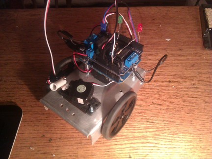
added a better cowel to the PR, by chopping up a pen with a dremel. And added "direction" LEDs, so i can test it on the desk without it wandering off! (there are seperate switches for the duino, and the motor shield)
Finds light, but using a single PR
- Actuators / output devices: 2 servos, 2 geared motors
- Control method: autonomous
- CPU: Arduino
- Operating system: Ubuntu
- Power source: 9V for logic, 4xAA Ni-MH
- Programming language: Arduino C++
- Sensors / input devices: line follower, single Photo resistor mounted with a three pin interface, repurposed for edge detection
- Target environment: Indoors - Carpet