


Crumbot
UPDATE: NEW VAC, CHASSIS, ETC. NO NEW VIDS :(
The ever-popular autonomous, self-charging, vacuum robot. Inspired by the old OMNI magazines photovore, of all things. The initial plan was humble and completely over-zealous using a BEAM inspired solar setup. It's evolved into a PICAXE driven battery powered robot to overcome my knowledge deficit of BEAM technique and solar power.
Crappy vid but you get the idea -->
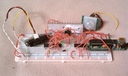
My humble PICAXE
Project plan:
- Design and test locomotion.
- Source low-voltage but effective vacuum unit.
- Develop and test charging circuit.
- Fabricate prototype robot base to test system interfunctionallity.
- Test IR communications protocol for charging station homing signal.
- Fabricate charging station.
- Design and test RTC circuitry for feasibility on an unregulated power source.
- Iron out the myriad of creases.
- Celebrate my first MCU success!
Project blog here
Materials:
- PICAXE 28X2 for robot brain
- PICAXE 08M for charger brain
- L293D motor driver
- GM17 228:1 motors
- cheap Ebay servos
- Old design short-range analog Sharp IR sensor (GP2D120?)
- MAXIM 712 NiMH charger chip
- 4xAA batteries + plastic holder x 2
- eBay novelty vacuum
- Power Dash slot car motor Upgraded Mabuchi motor
- 12V 1A 5A DC wall wart
Photolog:
- Design and test locomotion.
Let me say upfront that I don't have that many pics of this project. I intend on keeping a better photolog as the project continues.
The locomotion testing was done on an alpha test base with just the GM17s, the PICAXE 28X2 breadboard, and the Sharp IR sensor with servo riding on the back. It uses coding very similar to the first robot design ala Frits (thanks Frits!).
Prototype base with motors (left) and alpha base (right):
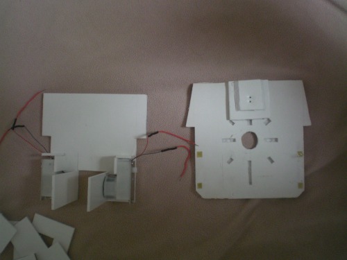
You can see I whittled out some holes in the foamcore I used for the alpha base to accomodate the bristles on the vacuum I ended up choosing. The prototype base has part of the debris box/nozzle apparatus assembled.
2. Source low-voltage but effective vacuum unit.
The first plan was to have a USB vacuum running off a regulated 5V from a common 7.2V battery pack with the 5V PICAXE running off its own regulated line. My first choice was this classic piece off the internet:
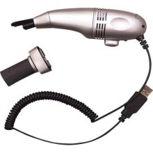
Per all the reviews it doesn't offer much suction. I only gave the chinese 3USD for it so I don't feel so bad. It's selling point was that it had the perfect upright design that used very little space in the robot.
I decided to look into the 2 x AA battery powered vacuums out there. I ended up buying one of these:

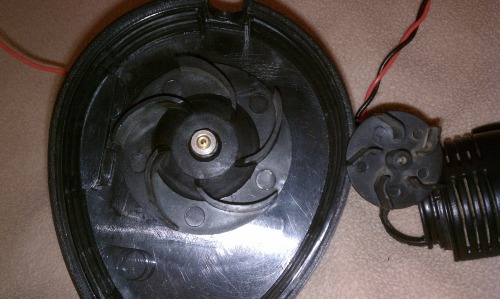 Surprisingly it works pretty well (at 3V). Even though it's driven by two AA's it has an impeller about twice the diameter of the USB vacuum I originally purchased. Despite the increased vacuum it still didn't quite cut it. I noticed it has the same motor can as the first vacuum I chose (Mabuchi 130 type) so I upped the voltage on the Magic Bug to 5V and it was pulling a vacuum the way I wanted. I proceeded to make the alpha base to test things and it worked ok. I was letting the bot motor around sucking up hair and crumbs to measure run time when the motor started smoking. I guess the increased voltage was too much.
 A was getting a little miffed at how the vacuum I wanted needed voltage that killed the motors I was using. Looking at specs for the 130 motor I stumbled onto a Chinese trend. Apparently slot cars have made a comeback over there and a popular scale uses 130-sized high RPM motors running at 2.4V. I was regulating voltage to the vacuum through a LM2576 that maxes out at 3A so I bought a Power Dash motor that uses current somewhere south of 2.5 amps I think it was. Swapping it into the vacuum I found the impeller causes more drag than the slot car it was rated for and it drew more current than the regulator could handle.
3. Develop and test charging circuit.
From the onset of this project the charger was to be onboard the robot and the charging station itself was only to supply the DC power. The activation of the charging electrodes would be handled by a PICAXE 08M monitoring reflectivity sensors on the station. The 08M would also send commands to the robot via IR. However at this point two things were causing me problems: 1) The noise from the vacuum was giving the Sharp IR distance sensor and its servo fits and 2) When hooked up straight to two 2300mAh NiMH batteries the vacuum pulled even harder than off the 2576 (batteries got very hot though). I could never solve the noise feeding back to the PICAXE so I changed the setup to use two battery packs; one for the vaccum (2xAA) and one for the PICAXE (4xAA). Plans are to use the ADC capabilities of the PICAXE to monitor its own voltage and a MAX8212 to send an interrupt to the MCU when the vacuum battery pack get low. A downgrade in motors is also probably necessary to prevent overheating the vacuum's battery pack.
This complicates the charging scenario more than I anticipated. Now the plan is to swtich between two charger circuits on the station, one for each battery pack, and a latching relay onboard the robot to dictate which battery pack gets the incoming charge current.
4. Fabricate prototype robot base to test system interfunctionallity.
As one can see in the very first picture with the two robot bases, the design changed somewhat. The alpha design was for ease of vacuum testing but was not feasible for the prototype. The robot is intended to stay under 6" x 6". As it stands it will measure just a hair over 5" sq. With the vaccum flat it was hard to easily remove the vacuum to empty out the debris with the batteries and/or circuit board likely to be above the vacuum itself. Plus the collection area for the debris is not that big.
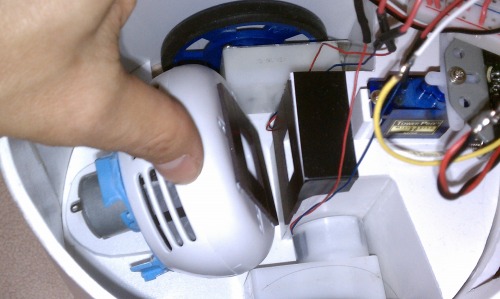
I decided to turn the vacuum on its end and have it draw air through a nozzle into an intermediary debris chamber that would be emptied by opening a door on the front of the robot, eliminating the otherwise necessary disassembly/reassembly process.
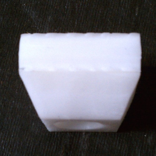
Pics of partially assembled vaccum stack:
The extra pieces are mostly to box off the vacuum exhaust, which will be directed out the top of the bot This will eliminate the exhaust blowing out the bottom of the robot, pushing the dust away as it approaches. The vacuum stack design is hard to describe. On the bottom of the vacuum (around the inlet) there will be a magnetic seal that will attach the vacuum to the debris box. 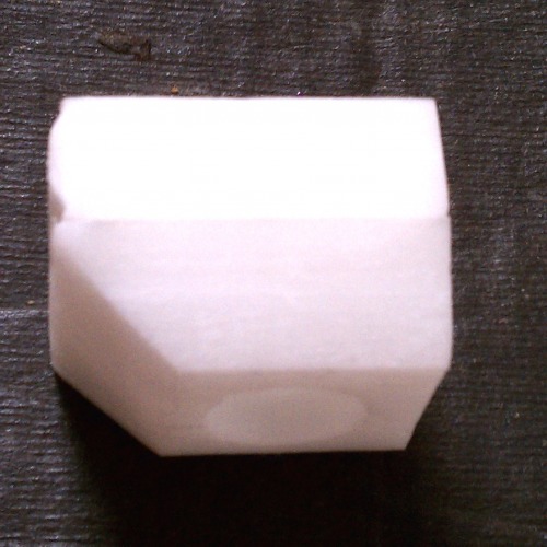
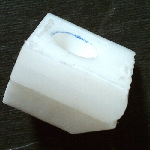
The nozzle is formed from a block of Delrin nylon (actually two sheets glued together) contoured to be able to glide over the uneven surfaces it will encounter. I used a rotary tool to get the basic shape seen in the above pics. I still have a little work to do. The "hose" between the debris box and nozzle will be a piece of collapsable foam that has a sealed inner lining. The foams job will be two-fold. One, to provide a sealed, unobstructed airway. Two, to extend and collapse as the nozzle follows surface imperfections. On level ground it will be slightly compressed allowing for 1/4" extenstion into depressions it drives over.
My first test was with some random open cell foam (as seem above) used to pack test tubes used at my work. I used an old soldering iron to melt out a hole to match the box's base plate and the nozzles opening. Initial impressions were that it was harder to compress that I thought it would be so I burnt out the excess materials from the corners. I then sealed the inner surface with silicone caulking. It took more silicone than I thought it would and it stiffened the foam to the point where the bot couldn't compress it down enough to make contact with the ground. I'm looking for less dense foam and plan to seal the inside with a tube of plastic wrap (eg, Saran Wrap).
5. Test IR communications protocol for charging station homing signal.
Successfully programmed and designed the IR beacon seeking parts. The charging station will have a cluster of IR LEDs intermittently putting out a signal. Ordinarily it is ignored by the robot until either battery pack goes low. The robot will then start looking for the IR signal through the transceiver mounted on the head. When the transceiver finds the IR signal the robot will begin a sequence to center in on the signal and head towards it.
The charging electrodes on the robot will be a metal ball caster for the ground contact and a spring-loaded pickup on the top of the robot for the positive. The charging station will be a negative metal sheet on the ground and a postive metal sheet overhang (oversimplified description). There will be reflectivity sensors on the ground sheet that will detect when the robot has moved onto the charger. When the sensors are activated, the PICAXE 08M will change IR codes to one that signals the robot to stop and continue monitoring the IR signal. The charge sequence will then begin. The robot will be activated via IR when the 08M receives an interrupt from the MAX712 charger that signals the charge is complete. The robot will then begin its "back out" sequence and then resume cleaning. But only while I'm at work. All will be controlled by an RTC like the DS1337 (if I can get over the inaccuracy from my noisy supply lines).
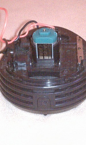
The popular 3V "mushroom" vacuum did prove to be underpowed so I swapped in another Mabuchi motor rated for more voltage and higher load. At stall it consumes 1.9A. No load (other than the vacuum impeller) and it consumes ~1A. My 2450mA batteries are much more happy with the situation.
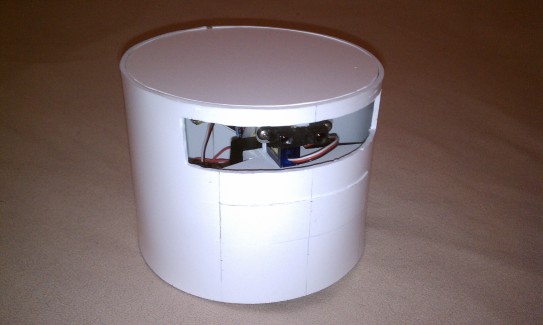
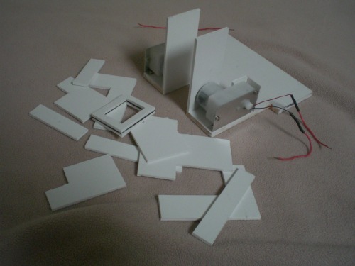
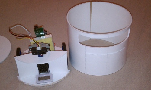
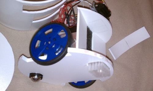
I have also fashioned a different chassis, doing away with the square prototype version I was working with. The reason for the change is two-fold: One, I just didn't like the whole look of a box puttering around my place, and two, I was getting tired of working out how to get the bot to maneuver away from things it ran into. It was always catching its corners on other obstacles when backing up and it was giving me fits.
The new design:

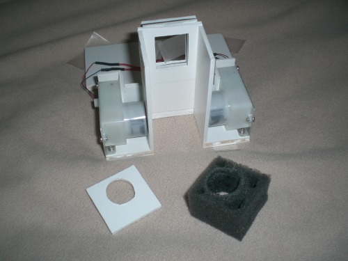
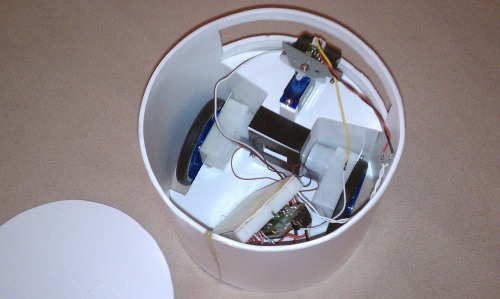
The internals minus the battery packs (they will be on the sides next to the vacuum:
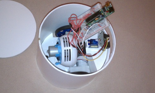
I used magnets to make an easy connection for the vacuum (the black is electrical tape to hold things down):
Insides, sans vacuum:
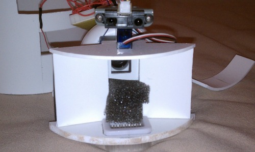
Pics with the outer shell removed to show the debris collection compartment:
Shell with the access panel to the debris compartment removed. I will secure it with magnets ala the vacuum connection:
Close up of the comparment. I grabbed some filter foam for freezer compressors from work (the black sparkly material) to catch the majority of the macro sized bits:
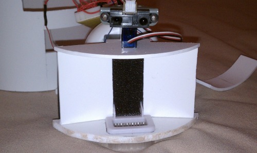
Pics with the foam peeled back (yes, it's two layers):
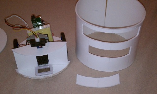
Shot of the underside of the beast:
I put the overly-complex vacuum nozzle to rest and went completely in the opposite direction. It's now as simple as possible by using one of the accessory brushes that came with one of the mini-vacs I've ordered. It's oversized considering the opening to the vacuum itself is much smaller but I've still yet to see the consequenses from going too big (read, hasn't been tested yet).
I'm currently working the bump sensors for the front:
They are two ultra-low force momentary tactile switches that will be supported with some silicone beads in key places between the bumper and bot body. There will be one for the left and for the right. These triggers should allow the bot to get as close to obstacles as possible to cover the most ground area.
I'm also working on the circuitry for the vacuum. It will be on its own 4AA NiMH pack with an ultra-LDO regulator keeping things at 4.5V (this eliminates the previous designs that used two MAX712s to charge a 2AA and a 4AA pack separately). All the bits are in my possession. Now I just need time and gumption to get this thing sucking!
Autonomously vacuum small debris and recharge
- Actuators / output devices: 2x Solarbotics GM17
- CPU: picaxe 08M, PICAXE 28X2
- Power source: 4xAA batteries, 2xAA batteries
- Sensors / input devices: tactile switch, Sharp IR sensor GP2D120, IR communication
- Target environment: indoor