


"Cross the gap" robot
As I promised, I open a new thread about my robot which compete on "Cross the Gap" challenge proposed by Winfieldrobotics, here on LMR.
The ideea was to build a robot to start in required 12 inch cube, cross the required 12 inch gap between two tables and revert to its initial state (challenge rules did not required this point) so it can cross an other gap again.
The robot was built on my previous robot platform -=eXplorer=- and have following configuration:
- Arduino 2009 + homemade shield
- 4 standard servos modified for continuous rotation
- 2 Sharp IR sensors
- 1 DC motor + ESC
- 8 wheels
- various pieces of wood and hardware.
To perform the cross over the gap, the robot extended a rear and a front arms to help main body made the cross.
To extend the arms it used two metal gears servos, modified for continuous rotation and conected to a nut and bolt ensemble which change it's length when bolt is turned.
The first version of mechanism was very powerful but very slow. In this configuration robot need 125 seconds to made the cross.
For second version I found two screws with a greater step, thus improving arms extend time - under 30 seconds.
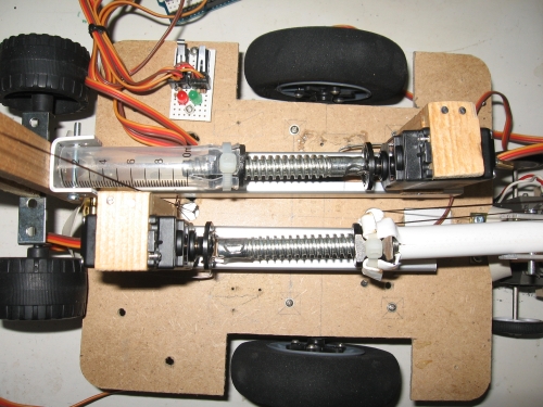
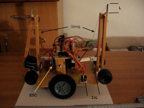
To extend the outer sections of the arms, I decided to not use extra actuators and use movement of the arms relative to robot base.
For this, I used two strings attached to robot base in one side and to outer sections of arms on other side.
At first version, lenght of strings and anchor point on robot base were not very well chosen and thus robot needs to be moved to allow rear arm to extend completely.
For second version these problems were corrected. You can see in the picture the correct ratio I found for my case.
An other problem, unfortunately not obvious for me from the start, due to complexity of the underside of robot, servos were attached to chassis with only one mount. At first this was not a problem, but after 20-30 up and down movements, the wooden mounts became more flexible, and at a moment the bolt from rear arm detached from it's nut so the main body fell on table at the same time when rear motor starts and the result was a pair of damaged gears :(
http://www.youtube.com/watch?v=TASJ3Bba3Hg
In the next picture I draw with green how I thought the mounts are pushed back and with red how they are really pushed. To correct this, I linked together the two loose sides of the mounts and finally everything was fine - on picture is a blue line where I mount the real link plate.

The process go as follow:
- Begin to extend rear and front arms.
- Meantime drive to the edge of table until front edge sensor detect the gap.
- Fully extend both arms and lift main body few cm above the table.
- Start DC motor from rear arm and drive forward until rear edge sensor senses target table.
- Put the main body down and rise the arms.
Once main body is raised, force on the wheels from end of arms is quite big, so DC motor needed a pretty high torque to move the robot.
This caused robot caught speed and until DC motor stops the rear arm is already over the edge and whole process was not as gentle as I liked.
First thought was to change motor with a servo, for higher torque at lower speed, but after initial shock :D I begun to like the quickness of the passing, since it was a speed contest, and let the DC motor ensemble as I made it from begining.
Unfortunately I lack the time needed to finish the last version of robot until the end of contest but it is a work in progress and I will post the results here when will be ready.
Here are the movies of the V1 and V2 passing the gap.
V1 - http://www.vimeo.com/20220600
V2 - http://www.vimeo.com/22774928
Cross the gap between two tables
- Actuators / output devices: 4 servos
- Control method: autonomous
- CPU: Arduino
- Power source: LiPo batteries
- Programming language: Arduino
- Sensors / input devices: Sharp IR
- Target environment: indoor