


cr3cX
Short description
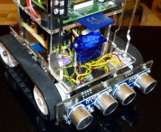
This is cr3cX, a robot I am building for my son to play with, and with the hope to teach him some programming. Current version is cr3c4.
Features and specifications:
- base board with ATmega168 with optiboot bootloader;
- tiltable support for a mobile phone or a webcam;
- support for a Raspberry Pi board;
- RGB LED controlled by PWM - 262144 colors;
- TB6612FNG motor driver;
- two brushed motors controlled by PWM;
- ultrasonic ranging sensor;
- two IR distance sensors;
- two switching power regulators;
- 2 x 16850 Lithium rechargeable batteries;
- laser cut body.
History
- cr3c1 was the prototype - my first tracked robot;
- cr3c2 had two IR floor detectors and two IR front detectors. It had a large blind area in front so I have discarded this design;
- cr3c3 had two utrasonic ranging sensors. It had some signifiant blind spots in front because the sensors have a very narrow view angle - design discarded;
- cr3c4 have one ultrasonic ranging sensor and two, front-right and front-left, IR sensors. Better detection of obstacles, I will keep this design for now, not having a better one.
Detailed desciption
Base board
As of 2012.09.18, the base board is done. To minimize the component count and complexity of the board I have changed my initial specifications and now the board have the following features:
- a socket for a TB6612FNG carrier board made by Pololu;
- drives one servo;
- drives a RGB LED - 262144 colors;
- monitors the voltage of the batteries;
- interface with a HC-SR04 ultrasonic ranging sensor using a single pin;
- interface for two home-built IR sensors;
- MCP1700T3302 3.3V voltage regulator;
- 3.3V I2C interface with BSS138;
- accepts commands through USART and/or I2C.
Base board software
Timer2 is used to control the motors.
Timer1 is used for servo control, RGB LED control and time keeping for ultrasonic ranging. For this I am using something I call "time slicing". A short explanation in the following picture:

Power
I use two Lithium rechargeable batteries, 16850 type, recovered from a broken laptop battery package. After charging them I've found that all the batteries where in good shape, maybe the pack's electronic was broken.
To regulate the power I am using two adjustable switching power regulators. One is generating 6V for motors and one is generating 5V for electronics and servo.
I am also using a liniar regulator for 3.3V output and I2C convertor as a provision for an accelerometer or a gyro.
Sensors
The distance sensors pack is not as good as I want it to be. It should be changed.
Android
I wanted to control the robot using an Android phone but I had to interface it:
- bluetooth is, in my opinion, just a dirty and temporary hack;
- the commercial shields/boards with USB Host and ADK capabiliKy are too expensive for this project;
- I am in the process of building a board with USB Host and ADk capability but it will take a lot of time, which I do not have, to finish it;
- writing the control software involves Java, which I like as a concept but I hate as implementation and some form ov video transmision, maybe through Skype, which again involves more time to do.
So, for now, the Android interfacing is on hold.
Raspberry Pi
I have modified a Raspberry Pi model A board to provide more power to the USB ports, by soldering wires over the PTC fuses placed near the USB ports. The power for Raspberry Pi is provided through the 2x13 pin connector. Now the board drives a wireless dongle and a webcam without an external powered USB hub.
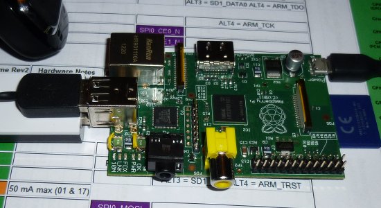
Raspberry Pi fuse mod
Communication with the base board is done through I2C.
Current operating system is Raspian updated as of January 2013.
The control software is made in Python with "web.py". Communication from the web page is made using JQuery and JSON format.
Video streaming is done using mjpg-streamer.
No security is implemented yet other that the software runs in an restricted account and not as root.
I hope that someone will release the software for the promised H.264 hardware encoding to make a full audio-video streaming from a webcam.
Pictures

cr3's Base board

cr3's Battery holder
cr3c3's sensors

cr3's Web interface

cr3c4
- Actuators / output devices: 1:60 small, Pololu like motors and a servor
- Control method: Autonomous and semi-controlled
- CPU: atmega168, Raspberry Pi
- Operating system: bare bone
- Power source: 2 x 16850 cells
- Programming language: C/C++
- Sensors / input devices: Infrared and ultrasonic sensors
- Target environment: indoor