


CNC Machine -- Valkyrie-Clone CNC
Old pic: https://www.robotshop.com/letsmakerobots/files/clone_cnc_closeup_1500px.jpg
TinHead's Original: https://www.robotshop.com/letsmakerobots/node/9006
Vector Drawings: https://www.robotshop.com/letsmakerobots/files/clone_cnc_vector.pdf (draft)
Measurements will be available for these drawings sometime over Christmas Break 2009 or if somebody asks me for it.
Specs:
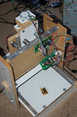
- ~175mm x ~115mm cutting area
- Cuts 4" x 6" copper-clad boards
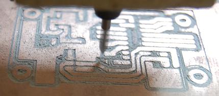
(http://www.oselectronics.com/ose_p56.htm) - Resolution: On a copper-clad board on a surfaced table, a fresh sharp 60° bit, and a carefully set cutting depth, I can get down to 0.4mm traces in the X-direction. To minimize errors I try to keep to 1mm traces or larger (1.4mm typical, with 1.6mm pads on vias). Traces can be made at 0.4mm between pads of a DIP IC if "0.12mm" isolation is selected from the pcb_gcode/pcb_gcode_setup plugin in EagleCAD.
- ~35mm Z-axis travel (allows boards to be stacked on the base)
- Cutting speed: I added some pauses to the RepRap feedrate code, so I know it isn't going as fast as the feedrate says it's going. However, I did surface a 110mmx160mm area with 1.2mm passes in about an hour with a ~2mm bit (cutting off about a millimeter depth of particle board off the surface) -- so about 256mm/minute for surfacing, corresponding to reported feedrate of 1000. On copper-clad board, with a 60° engraving bit, I have used a feedrate of 1400, but it could go faster. The feedrate of 1400 means ~360mm/min.
- Machine Dimensions: about 20"x17"x22" clearance (X,Y,Z) (0.50 x 0.43 x 0.56 meters) -- the base stage is 18" long by 12" wide with extra room on the sides for the motors/lead screws/X-stage which brings the Y-dimension out to 17" (from 12"). The motors on blocks extends the X-dimension to 22" (from 18"). (1" = 25.4mm)
- Measurements shall be added to vector drawings soon!
- Computer runs Inkscape with GCODE plugin for design, EagleCAD with GCODE plugin for PCB. Code executes on Chris Meighan's "GCODE for RepRap", running on Windows XP.
Documentation:
- Blog posts: https://www.robotshop.com/letsmakerobots/node/11287
- Vector Drawings: https://www.robotshop.com/letsmakerobots/files/clone_cnc_vector.pdf (draft)
- Part List: https://www.robotshop.com/letsmakerobots/files/cnc_partlist.pdf
- TinHead's Stepper Driver (modified): https://www.robotshop.com/letsmakerobots/files/tiny2313_stepper.brd (EagleCAD with SparkFun design rules
Tools for construction:
- Workmate Bench, Drill, Circular Saw, 500 pc (est.) drill set, coping saw for aluminum rails, tape measure, ruler
- Proxxon 12VDC Rotary tool for spindle, 36pc Dremel set including metal-cutting bits for cutting lead screws
- Soldering station
- Adafruit USBtinyISP AVR Programmer (plus WinAVR software)
- ISP target board with 16MHz Crystal Oscillator (pictures to follow)
- Wire cutters, pliers, linesman pliers, C-clamps, socket wrench, adjustable wrench
- (Circuit board etching setup or PCB trace routing machine or PCB vendor)
- EagleCAD with SparkFun Design Rules plugin (keeps traces from getting too close to each other)
Components:
- Adafruit DC Boarduino for control (requires FTDI cable) or Arduino Duemilanove
- Stepper-Driver components described in Bill of Materials https://www.robotshop.com/letsmakerobots/files/cnc_partlist.pdf
- 24VDC Stepper motors
- ATX Power Supply Unit, 300W or (http://www.rackmount-devices.com/045-6854.html, http://www.interinar.com/fs-15024-1m.html)
- 20' CAT-3 cable -- for signal wires (20' = 160' of 24AWG wire)
- 25' wire -- 20AWG for power wires
- 1/4" interior diameter clear tubing
- heat shrink (various sizes)
- 5/16"-18 fully-threaded bolts x 2" or longer (M8-1.25 equivalent, 60mm or longer) to fit the interior diameter of the skate bearings
- 40 inline skate bearings (e.g. "China Bones" and "ABEC-1" used for this machine)
- An IKEA nightstand worth of particle board/MDF -- or 1/3 sheet of particle board or MDF from the lumber yard
Cost: I built up my workshop while building this project, so it is hard to estimate the true cost. For folks who have access to a wood shop, an electronics lab, an AVR programmer, a circuit-board etching setup, creative part sourcing and a rotary tool, you can probably build this for $150 in about a week.
Code: Based on the Valkyrie CNC stepper driver/Arduino source code: http://github.com/TinHead/Valkyrie-CNC-source-code/tree/master. Perl Script loaded https://www.robotshop.com/letsmakerobots/files/serial_script.pl_txt, attachment to this page.
Prior Art:
- Valkyrie CNC: https://www.robotshop.com/letsmakerobots/node/9006
- $250/$350 CNC: PCB mill and Gantry mill from http://bluumax.com/ (USA)
- $600-$800 CNC: Sable-2016 PCB prototyping CNC on ebay (lukechan66), (incl. ~$100 freight cost to USA)
- $1100 CNC: Fireball V90
- $500-$1100 CNC: Mike Beck's CNC Router Kit at http://www.mikebeck.org/ (USA)
- $2900 CNC: http://buildyourcnc.com
- $???? CNC: http://www.cerebralmeltdown.com/cncstuff/mycnc/index.htm
- ATX PSU Power Supply: http://www.wikihow.com/Convert-a-Computer-ATX-Power-Supply-to-a-Lab-Power-Supply
Tricky Parts:
- Setting the ATTINY2313 "lfuse" to a 16MHz oscillator: "lfuse" to "0xFF"
- Aligning the lead screws: I used floating blocks that were aligned at each end and screwed down. (https://www.robotshop.com/letsmakerobots/files/clone_cnc_floating_block.PNG)
- General alignment problems: Of the four rails used for X-stage travel, the two rails on the top and bottom of the base-stage should be parallel to <1mm, and the rails on each side of the base should be parallel to ~1mm.
- Aligning the X and Y axis: the X and Y stages should be perpendicular to each other to 1mm over the runout of the stage: "Clone CNC" has 3mm of Y travel over the 165mm X runout :( I'm not sure whether it'll be a problem while drilling holes in PCBs
- Alignment of the Z-axis -- the floating block may not be possible, or may have to be positioned on top of the stage near the motor. Good alignment will make it easy to lift the stage. Bad alignment will make it difficult for the little motors to lift the stage. Rails and screws should be parallel.
- Switching to 24V -- the ATX PSU is not meant to put out a whole lot of power from the -12V (blue) wire -- only about an amp from -12 to GND. You may only get one quarter amp to work with when you run the steppers on the -12V/+12V wires. The Clone CNC is running fine, but I have a spare PSU in case the current one dies from too much load on the -12V line.
- The Boarduino must be hooked up to the same ground as the stepper drivers -- run it from -12 to GND (GND is positive/high, and -12V is ground: confusing?) if you use 24V from the ATX PSU.
Kudos:
Credit where credit is due: My CNC is deeply indebted to TinHead's work on the motor driver (node/6967), driver software, Arduino controller software, and hardware design, along with the discussions on the "Valkyrie" robot page (node/9006). Driver software is http://github.com/TinHead/Valkyrie-CNC-source-code/tree/master . Somewhere in the driver and Arduino source code, the RepRap project gets kudos as well. Debt is also owed to http://buildyourcnc.com for some of the construction tips. I wouldn't be able to join the wood so well without learning good drilling technique (last time I joined more than 2 pieces of wood was in Middle School shop class in '93). Also, ladyada's AVR tutorial ( http://www.ladyada.net/learn/avr/ ) was essential to programming the ATTINY2313 used in the stepper drivers. The controllers were programmed on a minimalist target board from evilmadscientist.com ( http://www.evilmadscientist.com/article.php/avrtargetboards ).
Rear View: The picture above shows the Z and Y axis drivers, plus the homemade power and I2C terminal block. The +12V bolt is heat-shrinked in yellow, the -12V bolt is heat-shrinked in blue, and the I2C is bare (because it is >100x less likely to kill me or burn me). I chose a telephone-style terminal system -- wrap the wires around a bolt, between washers, and tighten. Fasten the bolt on an insulating surface (wood in this case) and mount the terminal in a convenient place (screwed onto the X-stage). The pairs of wires are not twisted together for neither power nor I2C pairs -- Instead I run the wires parallel and keep them seperated at a fixed distance with tape. I got the idea from outdoor "Ladder Line" antenna wires used in ham radio, for which you also don't want crosstalk between wires.
Update 19/11/2009: Trace routing on copper-clad board -- There were some lockups due to bad table surfacing and wrong choice of routing bit. Also, the machine was losing steps on the Z-lifting steps, so I added rubber bands and zip-ties until it stopped.
Update 21/12/2009: I loaded "serial_script.pl" as an attachment, which is a perl script to control the CNC. I improved my clamping system and re-surfaced the table. I still needed 60° trace-routing/engraving bits. Up-cut router bits are the wrong tool for trace-routing. In "serial_script.pl", the Perl script receives either no arguments, in which case it runs a script, or a GCODE command string, which it sends to the microcontroller. So >>./serial_script.pl "G01X10Y10" would step the CNC 10mm in the positive X and Y directions (along a diagonal). The 5-second delay is needed for the controller to initialize when the script starts. Also, there needs to be a "Serial.println("zomfg");" inserted in "arduino_gcode.pde" after initialization is complete or the script will never continue.
Update 24/12/2009: https://www.robotshop.com/letsmakerobots/files/clone_CNC_first_trace.JPG -- I got my new 60° trace-etching bits, a new Java application by Chris Meighan (http://www.chrismeighan.com/projects/g-code-for-reprap), courtesy of avantgps and with help from brickbatbae, and a vacation day to play with it all. I attached the second X-axis lead screw. I used the back of a used copper-clad board to test my new bits. The only problem was that there were empty lines in my GCODE file, so the GCODE for RepRap would send the line, but the arduino would not reply, so the script would not continue. There were no problems with the I2C failing. From start to finish, the board was routed and drilled without having to home the machine. As long as I make my EagleCAD boards with wide traces and big pads for the components, I should be able to use the pcb-gcode plugin to make circuits.
Update 29/12/2009: Guitar Effects Pedal Power Supply Project, for which I used EagleCAD and this beautiful little CNC. https://www.robotshop.com/letsmakerobots/node/13983
Update 09/Jan/2010: 83MB of photos of the Valkyrie-clone CNC at http://www.freakivy.com/clone_cnc_complete.zip
Update 25/Jan/2010: The CNC is hard at work etching and drilling new drivers for some bigger motors for a motor upgrade. It has been up and working for about a month now (since I got the 60° bits a little before Christmas). I am a little nervous about changing my machine since it works (it's fabricating its own drivers), and the little printer motors are kind of charming. I think I'll work on the control system and hold off on building (buying?) a new machine until the old one breaks or starts to fail.
Update 30/Jan/2010: The machine seemed to be failing. It became extra-sensitive to changes in current, for example, when the machine is cutting. I blamed changing my power supply from multiple supply wires to a single supply wire (I had my supply wired bundled at first, but then just used a single wire), and also blamed changing the drivers to be inside the box. I noticed TinHead made a change that seemed to help -- while moving the drivers inside the metal case, he upgraded to a 24V power supply. I was wondering if my seeming I2C problem was a power supply problem. Later, I remembered that I also moved the Arduino inside the box from on top. The final fix was to move the transformer brick for my Proxxon drill from the top of the machine to the other side of the machine, and to plug it into a different outlet. As of February I'm fabricating boards as good as or better than ever.
Update 11/Feb/2010: I made an 8-channel full-bridge rectified and regulated DC 9.0V power supply for my brother's many guitar pedals. Another brother will be making a pedal board, and the power supply will allow for no more 9V batteries. Also, I'm working on the machine upgrade -- I'm planning to change the control system from a smart 4x ATTINY2313 board to a RepRap v1.2 style stepper driver system with a single ATTINY2313 working as a multiplexer via I2C. I'm cutting the ATTINY2313 multiplexer board now. The multiplexer will take an I2C command from the Arduino and move one of the stepper drivers. Since there are 9x digital channels controlling the steppers, I wanted to move these wires to a dedicated board off the Arduino. The three-wire drivers (x3 unique channels) will be clipped into the ATTINY board. Schematic attached. GCODE files need to be relabeled from ".nc" before I can attach them.
https://community.robotshop.com/uploads/j/o/john-ny/imported/tiny2313_multiplexer_brd.png
https://www.robotshop.com/letsmakerobots/files/tiny2313_multiplexer_sch.png
https://www.robotshop.com/letsmakerobots/files/tiny2313_stepper_0.sch
https://www.robotshop.com/letsmakerobots/files/tiny2313_stepper_1.brd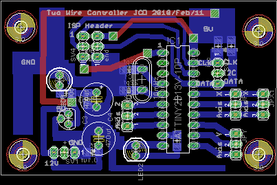
Update: 17 August 2010 -- New Drivers!
The short of it is that I got the Valkyrie-clone CNC working with new drivers (https://www.robotshop.com/letsmakerobots/node/15686).
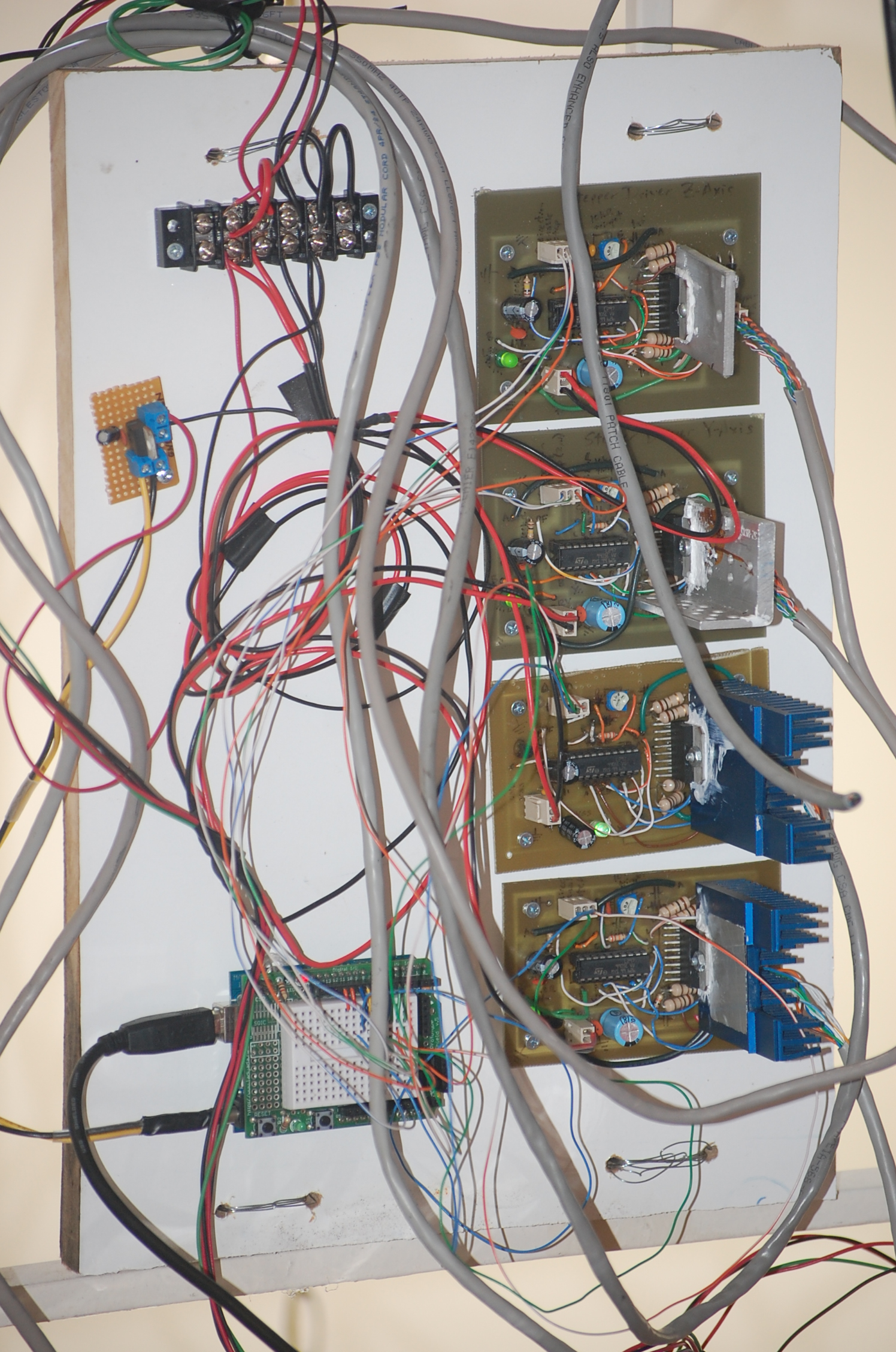
In the picture from top-left, clockwise to bottom-left: the terminal block (24V power up to 13A), the 2 X-axis drivers, the Y-axis driver (blue heat sink), and the Z-axis driver (blue heat sink), the Arduino controller (direction x3/enable x3/step x3), and just below the terminal block there is a small 9V regulator board to shift 24V down to 9V for the Arduino. Everything is mounted on an MDF board, and the board is mounted with baling wire.
More to follow, but it seems to work fine.
Cut, engrave and drill using GCODE scripts
- Actuators / output devices: cheap stepper motors driving threaded rods
- Control method: Serial control, Atmel microprocessors, L298
- CPU: ATtiny2313, adafruit Boarduino
- Operating system: Windows, for design, Scientific Linux, RHEL, Perl script, for scripting
- Power source: ATX PSU, 300W
- Programming language: Arduino C, AVR C, Perl, GCODE
- Sensors / input devices: Limit Switches
- Target environment: Indoor/Outdoor, well-ventilated areas