----------------------------------------------------------------------------
I now have my PSU. And i think im going to use a gripper and not an electromagnet.
I still need to go get some wood to start building but i think ill start this weekend. Oh i also got my shift registers.
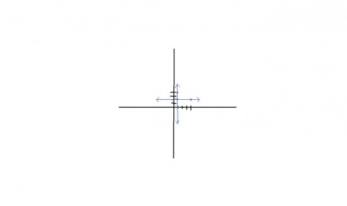
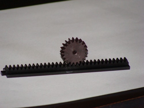
Here is a drawing of how im making the gripper raise and lower. I still dont have a design for the gripper itself. You can see that it raises and lowers using a rack and pinion. It slides up and down on a rod and the whole thing slides on a "sled" over the board.
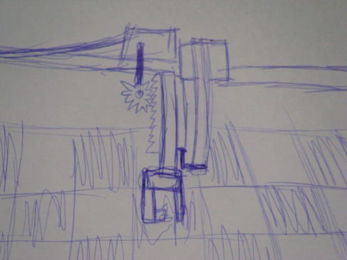
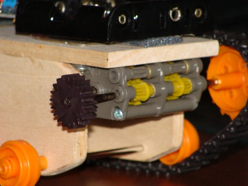
The gear for the rack and pinion fits tightly on the tamiya dual gear box that is on one of my robots. So i will be buying one to use on this robot that will move the "sled" and arm.
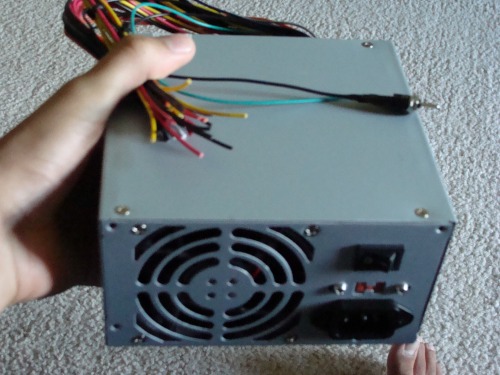
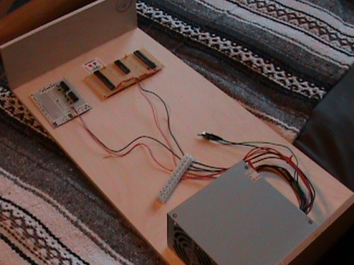
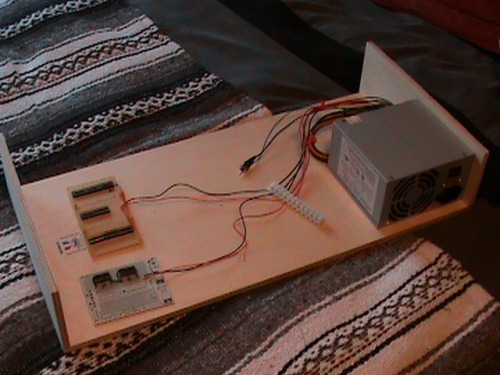
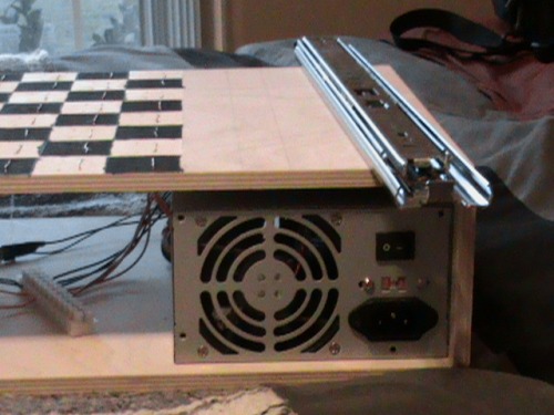
My modified power supply is finished. A 10w 10ohm resistor was added on the inside (bye bye warranty) as a load. And a switch was added. All the connectors were cut off.
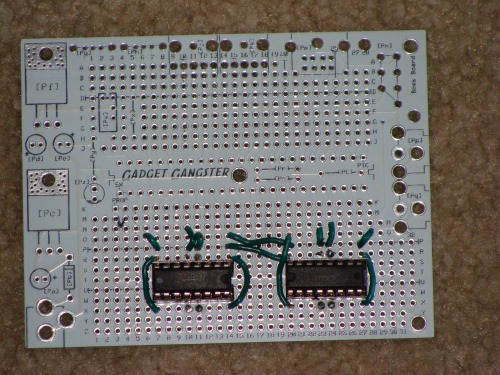
Here is my motor driver board. It is just 2 l293d's with the ground and power wired up. It will be able to drive 4 motors. I also have a chip for the servo which i will add later.
----------------------------------------------------------------------------------------
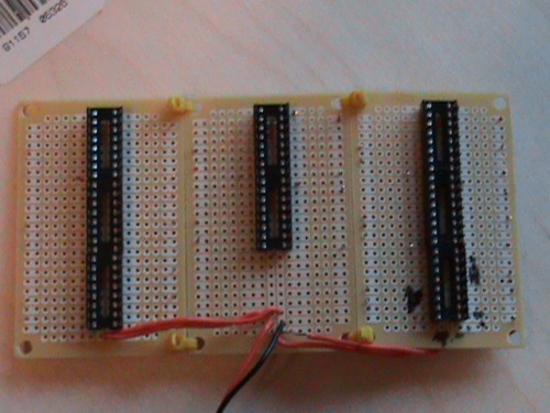
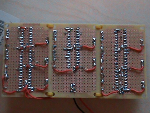
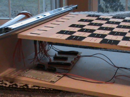
Here is my board for my 8 parallel to serial shift registers. The back is all the traces made for the chip and for the pullup resistors. They are 3 radioshack boards zip tied together.
 \
\
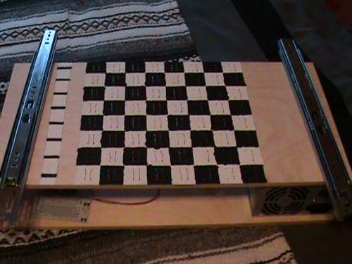
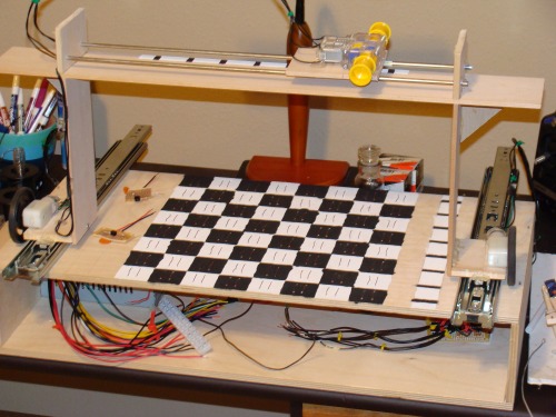
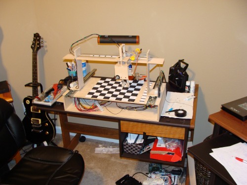
Below are pictures of the base of the chess robot where all the electronics are housed. It is not complete yet. It is missing the xmos board. The base is made out of thin plywood and just nailed and glued together. It is 12"x24"x4", so its not too big or small.
Ok so below is all of what ive done so far all together. I got 2 drawer rails to use as the base of the gantry crane. They have very low resistance so i hope the gms' can move the crane. That is about the exact lay out so not much in looks will change besides the crane which is the next big part. I cant build the crane till i finish the base.
----------------------------------------------------------------------------------------------------------------------------------------------------------------------------------------------------
ok a lot of building has been done since the last update. This update may not be huge in size but in the amount of work that has been done.
lets start with what has been done since last time
-finished the shift register boards and the chess board sensors.
- built the gantry crane
-mounted all the motors
- made a sliding system on top
- built a gripper
-built a raising and lowering system
-painted last encoder
things left to do are:
-place encoder sensors
-mount the gripper
-long story but need new l293ds
-program
-add cool sound effects
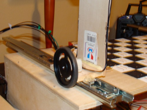
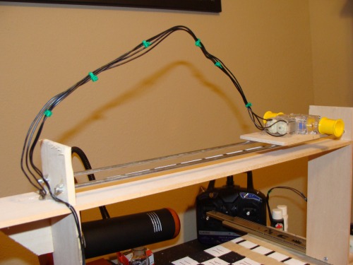
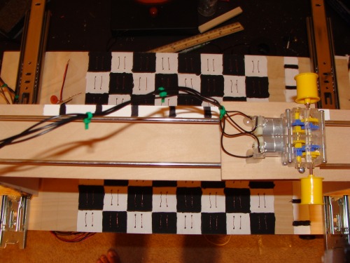
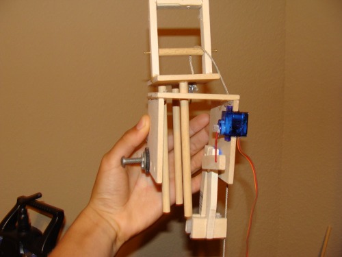
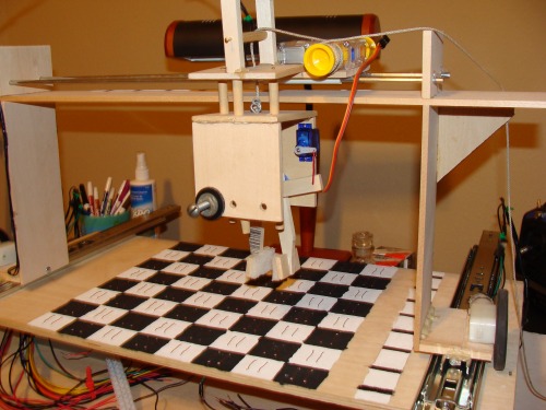
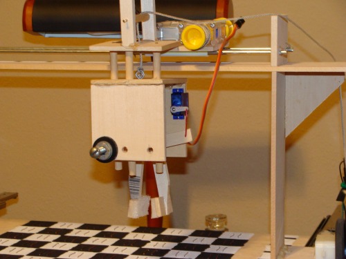
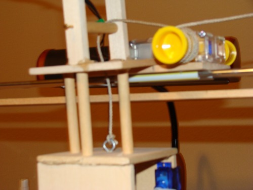
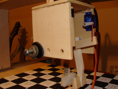
Lets get into some depth. The crane was built at 8 1/2" high X 17" long. The railing system on top is two metal poles with a carriage that rides on two tubes back and forth on the rails. A string will be looped once around the motors spool to move the carriage back and forth. The gripper was made using 2 gears i had left over from making the gear box. The rack and pinion idea was dropped and now it is lowered and raised by a string on a spool. There are 3 poles acting as guides for the gripper as it lowers and raises. The gripper is just short enough to not run into the king as it moves around. It has some counter balancing "weights" to make it balanced (duh). All the extra wire in the air is so the motors can easily move with some slack. The wires for the encoders and the servo must be added. I taped the gripper up in its position to show how it will look, that was just for demonstration purposes only. Some foam was added to the grippers fingers because it was no holding onto the pieces with out it. Well thats about it. The best part is all the pictures so here they are.
--------------------------------------------------------------------------------------------------------------------------------------------------
update 11.08.2009
well this is the second video. Basically the gripper is mounted and the working encoders are on. I am starting to have problems with the shift registers giving me 11111111. When it should be 11000011, it was working before. I do not know what the problem is but that is next to fix. The servo, i do not know what to on this. It just does not work. It only works when it is by itself in the main loop telling it to stay in a position. Do servos just stay in their positions when not told to do anything else?
the gripper is mounted but the string needs to be changed. The one i use stretches so i need to buy some good string. I bought a arduin mega.Sorry about all the clearing of my throat in the video. I think the solder fumes are getting to me ;)
--------------------------------------------------------------------------------------------
update 11.14.09
Well today i went to radio shack and bought some capacitor hoping that today i could fix my servo noise problem. Well thanks to telefox and his schematic
i was able to get rid of the servo noise making this whole update possible (putting him on the thank you list at top). But there are still a lot of problems with the robot. Some or code problems and others are physical problems. The code has not yet been good enough to allow the robot to go to every square mainly know because it goes 1 square past where told to go. The physical problem may provide that answer to the code problems. The string is very limiting, it is either too tight, too loose, but never perfect. So maybe the string idea will be abandoned. I have lots of problems with no ideas for solutions. I am working as fast as i can and at this pace my estimation for the completion of the robot is set for maybe April 2010 (very rough estimate, may be over estimating myself). More problems have come after that video. The motor that raises and lower the arm is getting stuck every now and then causing great strain on the motor and making the string wrap around the shaft.