Canis Majoris
Hello guys! This is my atempt to make kind of a rc boat, with some extra things inside.
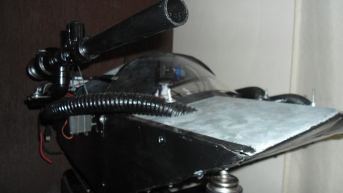
- Made of steel bars and some kind of metal foil (I dont know what metal is this, just know it is used to make gutters);
- 24v, 250w brushed, heavy and inefficient motor.
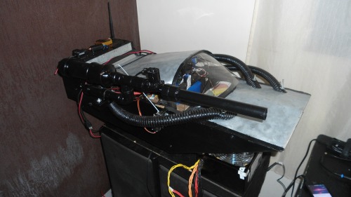
- Lipo 4s 5000mah that used to be a 6s (yah, I did shit);
- Arduino uno as a brain;
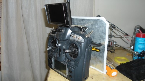
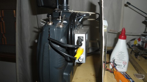
- Cameras for some kind of "FPV", with the receiver on the controller;
*Secondary camera on the botton of casc for watching the deep waters and get some meditation (lol?);
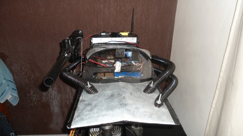
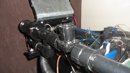
- Homemade Air gun;
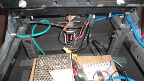
- Homemade Water pump in case of water getting inside of it;
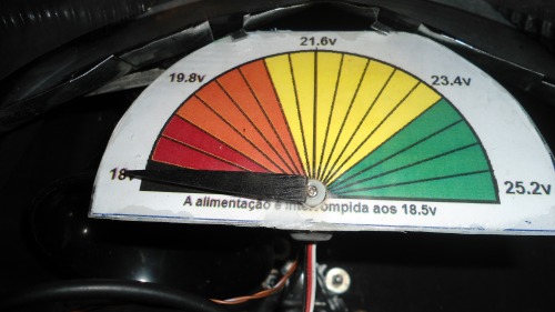
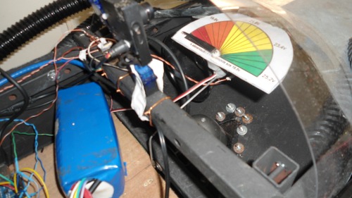
- Homemade voltage display (arduino reading and servo controlled display);
- Residencial kind of alarm to alert me when the battery starts to get a low level.
The arduino uno reads the channel 3 of my receiver and convert the ppm code to an analog output and write it where would be the central pin of a potentiometer in my pwm controller. It also reads the channel 5 and do some extra things.
I removed one of the potentiometers of my turnigy 9x and installed a couple of new push buttons. There we have a voltage divisor of multiples resistors, and in each node there is a button conected. When I press the button, it will send one fixed voltage wich I can map with arduino and configure the action I want. I have 3 buttons on this: change camera, dispare the alarm (I can use as a horn), reverse motor and pushing two buttons on the same time I can shoot the weapon.
The camera change is made by a relay bank where is inverted the power conection (turning off one camera and On ther other one) and also changes the pin that sends the video signal.
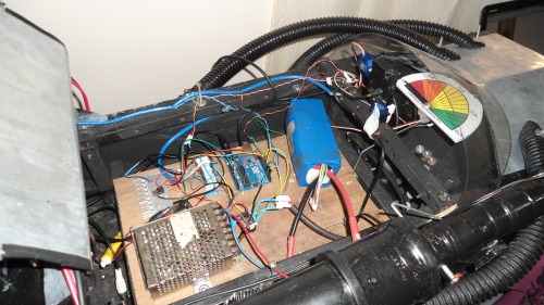 The motor reversion follow the H bridge relay concept.
The water pump on the bottom of the casc has two terminals next to each other, where I can read the eventual
presence of water and run the pump to drain all the water off. Controlled by the arduino.
Air gun is just that junk on the image D: .. pump some air with a bike pump and you are ready to go. Solenoid valve installed in it.
The voltage display... There is a voltage divisor on the arduino input, that lets only 1/5 of the voltage to pass through it.
So, the arduino reads that and (knowing that reading equals to 1/5 of the total voltage) converts to a mapped ppm code and writes on the servo wich controls the voltage display.
On the controller I have the camera image receiver and a lcd display. All running with one 3s lipo battery;
More photos:
Will upload videos soon.


