


building my RepStrap 3D printer from salvaged printer parts
In the ongoing saga of building my RepStrap 3D printer from salvaged printer parts...
Update in the blog section: https://www.robotshop.com/letsmakerobots/further-progress-framing-my-repscrap-3d-printer
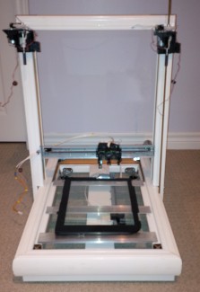
The first axis is sorted out:
This is the printhead carriage salvaged out of a inkjet printer. It basically consists of a DC gear motor driving a tensioned belt, pulling the print carriage across a high resolution optical encoder strip.
There have been plenty of people do this before me, but this is my kick at repurposing salvaged printer parts.
This is the print head circuit board from the carriage. In the center, you will see the solder pads for the Optical Encoder Sensor. My original intent was to keep the flat cables intact, and pull the signals off of those, but at about 50mil pitch... I can't even think about soldering that...
(yeah, I'm getting old)
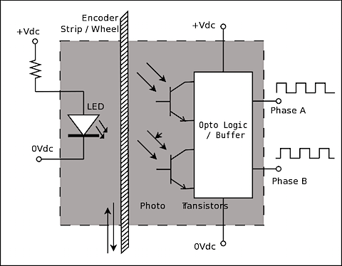
As they have already done the work of wiring the IR LED with a resistor to VCC, all I really need is four wires. VCC/GND/Encoder Phase A and B.
The Optical Encoder provides logic level outputs to the Interrupt pins on the Arduino. The sketch below only addresses the X-AXIS for demonstration purposes, and only uses one Interrupt on Phase A, while polling the signal level on Phase B. This provides half the resolution capable from this Quadrature encoder.
In a future article, we will demonstrate using PinChange Interrupts to get the full resolution from this arrangement.
Code in attachment below!
This is the endstop sensor circuit. I haven't wired it up to the Arduino as yet, but it is pretty straight forward.
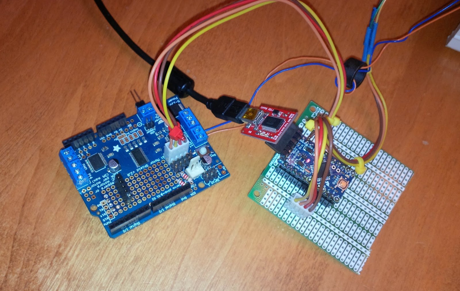
In the true nature of this project, I searched for a used motor controller to go with my Arduino . Pictured here, is the Adafruit I2C Motor Shield V2 that was on my original robot. This project will breath new life into it.
This is a wonderful board in that it contains TWO dual h-bridge FET drivers for four DC motors, or two steppers, or one stepper and two motors...
Wiring up the Optical Encoder. Only four wires are needed...
12volt DC gear motor used to drive the carriage assembly.
References:
http://playground.arduino.cc/Main/RotaryEncoders#OnSpeed
http://reprap.org/wiki/Optical_encoders_01
http://mechatronics.mech.northwestern.edu/design_ref/sensors/encoders.html
http://forum.arduino.cc/index.php/topic,17695.0.html
http://www.instructables.com/id/Improved-Optical-End-Stop/
http://playground.arduino.cc/Main/PinChangeInt
http://reprap.org/wiki/Microstepping_with_optical_feedback
3D Printer made from Salvaged printer parts...