


Brainless Line Following Robot
Sorry I do not have any pictures of this yet. I just got batteries for my camera this morning before work.
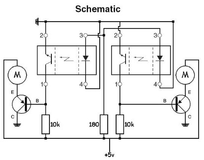
This consists of:
2x Fairchild QRD1114 Reflective Object Sensors
2x 10kΩ resistors
1x 180Ω resistor
2x PNP transistors
2x GM2 motors
The idea behind this is pretty simple. When the QRD1114 sensor sees the reflected IR light it has emitted, the phototransistor closes and sends current through to the PNP transistor which then closes and sends current through to the motor. When the QRD1114 sensor does not see the reflected IR light it has emitted, the phototransistor opens sending no current through to the PNP transistor. The 10kΩ pull-up resistor keeps the PNP transistor open, so that no current flows through to the motor causing it to stop.
When the QRD1114 sensor is pointing on the white background, the emitted IR light is reflected back, and the sensor closes. When the QRD1114 is pointing on the black line, the emitted IR light is NOT reflected back and the sensor opens.
The left QRD1114 sensor is connected to the left motor through the left PNP transistor. The right QRD1114 sensor is connected to the right motor through the right PNP transistor.
The 180Ω resistor is for the 2 IR LEDs inside the 2 QRD1114 sensors.
UPDATE:
Schematic has changed, PNP transistors were apparently upside down.