


"Bot" version 1
I am building a very simple skid steer bot. I am still in the "prototyping" phase and its body is currently made of recycled cardboard boxes. After unpacking any new hardware I never throw any boxes away, nice to see that I can actually put them to use. :) In fact I think I'll /keep/ it made of cardboard because I really like the looks of it.
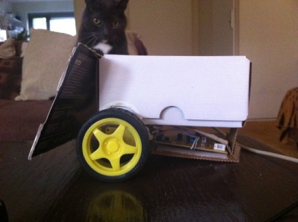
It is my first ever attempt at a robot and very much a work-in-progress. Initially, it looked like the picture at the right.
At the front is the bump detector. It was smaller initially, and it did not prevent the wheels running into small obstacles and stopping the bot, so I had to make it at least the width of the robot itself. (Even smarter would be cutting the bump detector into two halves so I can detect on what side the bump is and act accordingly.)
For brains it uses an Arduino Uno; the motors are controlled by a homebrew L293 board, which I soldered together on a Decimillia breakout shield.
This board also has a piezo buzzer on it, fixed to pin 13, which is excellent for simple feedback.
The jumpers allow me to hard-wire or to hard-disable the H-bridge itself and freeing up 2 pins if I need them.
The flat-cable you see in the picture should be exposing all the unused pins (at this point only pins 8, 10, 11 and 12; digital 7 and analog 0..3 are not yet connected).
All digital sensors, like its bumper detection sensor, are going to be connected through an I/O expander (an MCP23016), that connects to the exposed SCL and SDA at A4 and A5.
Update
It has gotten an optical movement sensor upgrade yesterday -- the inners of an optical mouse is being dragged along:
The idea being that it can detect and confirm movement. And so can detect whether it's "stuck" and stop motors running.
Also, this sensor can kind-of detect the the lack of a surface (i.e. being picked up). It's tricky getting the code right for this, what works right for shiny white surface does not work right for a black non-shiny one, but I guess that's a matter of further experimentation.
Update2: This code is running much more stable ever since the DC motors are fed from an external battery pack (rather than taking its juice from the Arduino 5V). Apparently the mouse was turning off and on the moment the motors wanted to have some extra power, making it's functioning terribly unreliable.
If it is "stuck" and then "picked up and put down again", it will decide to attempt to drive again. The red glow of the sensor really looks nice!
Update2: The optical mouse sensor has been moved a little towards to front making room for an old rounded cap of some hairspray can, which better serves as a third wheel rather than a piece of cardboard:
- Measuring distances (done)
After some measuring and experimenting and averaging the mouse's resolution, I can now tell my robot to move an arbitrary distance which it'll attempt to measure with the mouse sensor.
- Auto calibrating of motors (done)
I am still working on the "auto-calibrating" code that shall make sure it drives in a straight line by regularly checking the movement and force-correcting the power supplied to the right or left wheel to correct any errors. It would still drive 'wobbly', but roughly in a straight line, which works for me just fine.
- Bonus feature: 180s, 360s, 720s (planned)
I also realised the optical sensor can be abused to confirm whether a request for a 180 (U-turn), 360 or a 720 has been fulfilled. Knowing the radius of the circle that the optical mouse makes around the center of the axle; and knowing the angle, I can calculate the expected delta-X and delta-Y [sin(angle)*radius] and know when to stop it.
This would, at least in theory, work much better than simply "timing" how long it takes to make a full circle; using the sensor it would work regardless of the speed of the turn.
Update 2011-04-20
The auto-calibration code works now. Roughly like this, in case you are curious:
- The speed-apply code will check for a left_wheel_correction value and apply that to said wheel (motors driven by PWM so this is a possibility).
- The robot code itself will calculate heading regularly from delta-X and delta-Y feedback from the optical sensor,
- If it finds this heading to be in the left direction, make left_wheel_correction value higher. If we go to far to the right, make the value lower.
Initial testing looked good but when unconnected from debugging serial, it suddenly went haywire and turning in circles! Found that last bug in the code last night: it repeatedly kept correcting the left wheel so much it even started turning backwards -- I was basically adding the left_wheel_correction value twice!
So far, I am very happy with how it performs. As long as it has a good surface to track its movement it is much more accurate than I initially imagined.
The calibration code gets its heading value from a generic class I wrote to track movement. I decided that would be wise, for re-use in later projects (I'm a full-time coder, so I'm properly "conditioned" lazy that way).
It can be fed delta-X and delta-Y regularly from any sensor that is able to give such data (think encoder wheels in stead of optical mouse). If it is passed the correct resolution (i.e. units-per-meter), it gives some decent "human-readable" values to work with as well.
(While I wrote some bits of that code, I couldn't help reminiscing about those "mouse odometers" that people had running on their Windows desktop. Those really only make sense if the mouse is stuck on the underside of a robot!)
And talking about good surface -- that is the biggest issue of this bot at this time: the surface has to be flat. It can run dead on a slight bump (perhaps this can be prevented by tweaked the front bumper detector). Also, the grip of the wheels is horrible on carpet so it thinks it is stuck all the time. (That sucks, because now it cannot harrass our cats. :D)
I already moved its center of gravity by placing the 5 AA battery pack above the axle for more grip. Better -- but on carpet the underside still sticks.
I really ought to build the real chassis from a proper material soon... that may solve some of those "sticking" issues. I'm looking at plywood or something similarly "easy" to work with... I got plenty of metal bits, like casings of old computers, but lack the proper tools (and experience really).
I also added an extra button to serve as a "go to sleep"-switch to be able to turn the thing off if it goes haywire in the future. It bails at the right places in the code if it sees it high, and if it's pressed at least 2.5 seconds later, it shall awake again. This addition has already repeatedly proven to be useful!
So far, all my homebrew code is using up 16K of the 32K that's available on the Arduino UNO, didn't expect to hit it that soon. It's still ridden with Serial.print()'s without a propert #ifdef around them, so cleaning that up will shave a few Ks off..
Scavenged parts
I am Dutch, so I try not to put too much money into it, if possible, I try to find useful parts by scavenging old hardware. The following items have been "recycled":
- bump detector at the front is actually a switch from an old CD drive to detect whether the tray is open or closed, 3.5" floppy disk drives,
- the "movement" sensor is the sensor from an old optical mouse, which is being bit-banged by the Arduino to sense movements and a lack of a surface to drive on (i.e. being picked up).
Bump into things -- but in a very straight line!
- Actuators / output devices: 2 motors
- Control method: autonomous
- CPU: Arduino
- Operating system: Arduino running homebrew code
- Power source: 9VDC battery for 5VDC regulated supply, 5 AA-cell battery pack for motors
- Programming language: C++, C
- Sensors / input devices: bumper switch, optical mouse IC
- Target environment: indoor