


A video of BONES dancing is available here (link)
This will be the perfect project for those interested in learning how to program servos to make the Robot perform whatever dance routine you want it to.
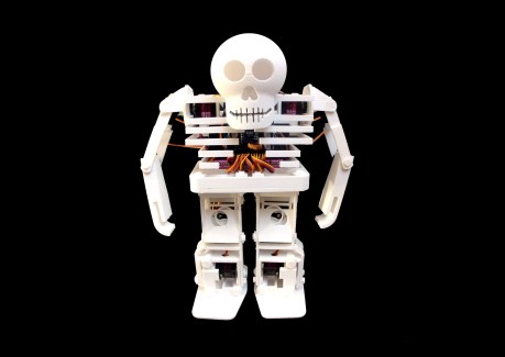
BONES costs just over 150$ to build batteries and charger included
BONES is controllable with the 3D printed Arduino Controller
he can move forwards, backwards, left, right, right kick, left kick, dance 1, dance 2
or he can perform a dance without the Controller
Enjoy the Build Instructions !!!
To build this robot you will need:
- 12x Genuine Tower Pro MG90S analog 180 deg servo (link here)
You can go cheap from china on a lot of things but servos aint one of them! After testing many differenet types especially cheap counterfeit towerpro servos I found out that the cheap counterfeit ones are so unreliable and often break a day after using so I decided that genuine towerpro servos would be the best!
- 1x Sunfounder Wireless Servo Control Board (link here)
You can't find a better prototyping board than this one for wireless servo control. This board has a built in 5V 3A power converter and 12 servo input pins and pins for a wireless nrf24L01 transceiver module and Arduino NANO all in a condensed neat package so don't worry about messy cables all over the place anymore!
- 1x Arduino NANO (link here)
- 1x NRF24L01 Transceiver Module (You don't need this if your not using the controller) (link here)
- 2x 18650 3.7V Li ion batteries (link here)
- 1x 18650 Battery holder (link here)
- 1x Li ion Battery charger (link here)
CONTROLLER:
To control this Robot manually you will need the 3D printed Arduino Controller (link here)
The Robot can also be purely autonomous so the controller is not mandatory.
PLASTICS:
The parts can be printed in PLA or PETG or ABS. !!
Please note a 500g spool is more than enough to print 1 Robot !!
3D PRINTER:
Minimum build platform required: L150mm x W150mm x H100mm
Any 3d printer will do. I personally printed the parts on the Creality Ender 3 which is a low cost 3D printer under 200$ The prints turned out perfectly.
So now it's time for Printing...Yeay
I Meticulously designed all of BONES's parts to be 3D printed without any support materials or rafts required while printing.
All the parts are available to download on Pinshape (link here) and MyMiniFactory (link here)
All the parts have been test printed on the Creality Ender 3
Material: PETG
Layer Height: 0.3mm
Infill: 15%
Nozzle diameter: 0.4mm
The parts list for BONES is as follows:
1x BODY BOTTOM
1x BODY MIDDLE
1x BODY SPINE
6x BODY SQUARE PINS
1x ELECTRONICS FRAME
1x ELECTRONICS SQUARE PIN
1x RIB BOTTOM
1x RIB BOTTOM MIDDLE
1x RIB TOP MIDDLE
3X RIB TOP
4x SMALL VERTEBRE
1x BIG VERTEBRE
1x FRONT SKULL
1x REAR SKULL
1x SKULL SQUARE PIN
1x SHOULDER
1x ARM
1x FOREARM
1x SHOULDER (MIRROR)
1x ARM (MIRROR)
1X FOREARM (MIRROR)
4x CIRCULAR ARM PINS
2x FEET
2x ANKLES
2x LEG 1
2x LEG 2
2x PISTON CASES
2x PISTON CASES (Mirror)
4x PISTON HOLDERS
4x PISTONS
2x HIPS
8x CIRCULAR PIN L1
2x CIRCULAR PIN L2
2x CIRCULAR PIN L3
10x CIRCULAR PIN L4
13x SQUARE CLIP
22x CIRCULAR CLIP
Each part can either be printed as a group or individually.
For Group printing all you have to do is print one of every single GROUP.stl file apart from the Group LEG 1.stl, file and the GROUP CIRCULAR PIN.stl files of which you have to choose one of them and you will have the entire set of parts required.
Follow the following Steps for printing all the STL files.
Start by printing the LEG 1.stl files individually as these are the hardest to print they require a brim of around 5mm and one layer height around the part to avoid warping if for some reason the brim does not prevent warping print the LEG 1 WITH BRIM.stl file.
Print the INDIVIDUAL CIRCULAR PIN .5mm L1, INDIVIDUAL CIRCULAR PIN .75mm L1 and INDIVIDUAL CIRCULAR PIN 1mm L1 once printed test the pins in the holes of the LEG 1.stl that you previously printed and select the one that fits the tightest without being to tight to not be able to push through the hole If possible use the .5mm one as the tighter the fit the faster the Robot will walk.
Print the GROUP SHOULDERS.STL file don't forget to print it with an 8mm brim of 2 layer heights to make sure it prints correctly
Proceed to printing the rest of the GROUP.STL files
And there we have it about 2 days of printing later you should have all of BONES's Plastic parts.
BONES uses C programming in order to function.
In order to upload programs to BONES we will be using Arduino IDE along with a few other libraries that need to be installed in the Arduino IDE.
Install Arduino IDE on to your computer
Arduino IDE (link here)
In order to install the libraries in to Arduino IDE you must do the following with all the libraries in the links below
Click on the links below (this will take you to the libraries GitHub page)
Click Clone or Download
Click download ZIP (the download should start in your web browser)
Open the downloaded library folder
Unzip the downloaded library folder
Copy the unzipped library folder
Paste the unzipped library folder in to the Arduino library folder (C:\Documents\Arduino\libraries)
Libraries:
Varspeedservo library (link here)
RF24 Library (link here)
And there we have it you should be all ready to go In order to make sure you have correctly set up Arduino IDE follow the following steps
Download the desired Arduino Code from the attachements section below (Robot Controller.ino or Robot Autonomous.ino)
Open it in Arduino IDE
Select Tools:
Select Board:
Select Arduino Nano
Select Tools:
Select Processor:
Select ATmega328p (old bootloader)
Click the Verify button (Tick button) in the left upper corner of Arduino IDE
If all goes well you should get a message at the bottom that says Done compiling.
Now it's time to upload the code to BONES's brain the Arduino Nano.
Plug the Arduino Nano in to your computer via USB cable
Click the upload button (Right arrow button)
If all goes well you should get a message at the bottom that says Done Uploading.
So now it's time to Calibrate and start assembling the Leg servos to parts of BONES...
All the following Steps are depicted in the Assembly Video (link here)
Electronic Parts needed:
1x Arduino Nano
1x NRF24LO1 transceiver (only if using BONES with controller)
1x Sunfounder Wireless Servo Control Board
12x Genuine TowerPro MG90S 180 deg servos
1x Battery Holder
2x 18650 3.7V Li ion Batteries
Plastic Parts needed:
4x Pistons
4x Piston Holders
2x Piston Cases
2x Piston Cases (Mirror)
2x Hips
1x Body Bottom
1x Body Middle
4x Body Square Pins
4x Square Clips
Screws and Servo Horns needed:
12x long self tapering screws
6x short screws for Servo Horns
4x single arm Servo Horns
2x dual arm Servo Horns
Assembling the Pistons Instructions:
Place all 4 Pistons into the 4 Piston Holders
Slide the 4 Piston Cases over the Piston Holders as shown in the Assembley Video above
Position the 4 Pistons so as that the Pistons holes and the Piston Cases Holes are aligned
Insert the 4 Servos through the 4 Piston Cases holes
Fix the 4 Servos in place with 2 long self tapering screws per servo to the 4 Piston Cases (do not over tighten)
Assembling the Hips and Body Instructions:
Insert the 2 Servos in to the Body Middle part (Make sure to place them the right way around cables facing outwards)
Fix the 2 Servos in place with 2 long self tapering screws per Servo to the Body Middle part
Insert the 2 Hips in to the Body Bottom Part
Align the Body Bottom part with the Body Middle part
Secure the Body Bottom part to the Body Middle part with 6 Body Square pins (as shown in the Assembley Video)
Secure the Body Square pins with 6 square Clips
Electronic Instructions:
Plug the Arduino and NRF24L01 transceiver (optional) into the Servo Cotrol Board
Connect the Battery Holder wires (Red to Positive Black to Negative) to the Servo Control Board (Make sure the connections are the right way around)
Connect the Servos to conections 4,5,6,7,8 and 9 in any order you want (Make sure to get the connections the right way around)
Insert the Batteries
Push the Servo Control Board Button to the pressed position
Switch the battery Holder switch to the ON position
The Board should light up and the Servos should move to their 90 degree home position
Assembling the Servo horns Instructions:
Once the Servos have reached their 90 degree home position insert the Single arm Servo Horns in to the Pistons at a 90 degree angle (+- a few degrees of offset is not the end of the world) to all the Piston Cases as shown in the Assembley Video above.
Insert the Dual arm Servo Horns in to the Hips so as that both servo arms are in line with each other. As shown in the Assembley Video above
Secure all the Servo Horns to the Servos with 1 short screw per Servo
Switch the battery Holder switch to the OFF position
Disconnect the Servos from connections 4,5,6,7,8 and 9
And there we have it all the Leg Servos are calibrated and the rest of the Robot is ready to be assembled.
All the following Steps are depicted in the Assembley Video (link here)
Plastic Parts needed for Left Leg:
1x Left Foot
1x Ankle
1x Leg 1
1x Leg 2
2x Assembled Pistons
4x Circular pins L1
1x Circular pins L2
1x Circular pins L3
3x Circular pins L4
9x Circular Clips
Left Leg Assembley Instructions:
Slide the 4 Circular pins L1 through the Ankle holes (As shown on the Assembley video)
Position one of the Assembled Pistons into the slot of the Left Foot select the Assembled Piston that makes the Servo cables face backwards (As shown on the Assembley video)
Position the Ankle on the slot of the Left Foot and the slot of the Assembled Piston
Slide 1 Circular pin L2 through the Ankle and Foot joint
Slide 1 Circular pin L3 through the Ankle and Assembled Piston joint
Slide 1 Circular pin L4 through the Foot and Assembled Piston joint
Position the Leg 1 in place on the Ankle and Circular pins L1
Position the Leg 2 in place on the Ankle and Circular pins L1
Position one of the Assembled Pistons in between Leg 1 and Leg 2
Slide 1 Circular pin L4 through Leg 1 and the Assembled Piston
Slide 1 Circular pin L4 through Leg 2 and the Assembled Piston
Secure all the Circular pins with Circular clips
Plastic Parts needed for Right Leg:
1x Right Foot
1x Ankle
1x Leg 1
1x Leg 2
2x Assembled Pistons (Mirror)
4x Circular pins L1
1x Circular pins L2
1x Circular pins L3
3x Circular pins L4
9x Circular Clips
Right Leg Assembley Instructions:
Proceed the same as the Left Leg Assembley Instructions.
All the following Steps are depicted in the Assembley Video (link here)
Electronic Parts needed:
4x Genuine TowerPro MG90S 180 deg servos
Screws needed:
4x Long self tapering screws
Plastic Parts needed for Left Arm:
1x Arm
1x Forearm
2x Circular Arm Pins
Left Arm Assembley Instructions:
Insert the Circular Arm pin into the hole in the Forearm
Insert the Circular Arm pin into the hole in the Arm
Insert the Servo in to the Arm as shown in the Assembley video above
Secure the servo to the Arm with 2 long self tappering screws
Insert the Servo in to the Forearm
Connect the Arm and Forearm together as shown in the Assembley video above
Plastic Parts needed for Right Arm:
1x Arm (mirror)
1x Forearm (mirror)
2x Circular Arm Pins
Right Arm Assembley Instructions:
Proceed the same as with left arm assembley
All the following Steps are depicted in the Assembley Video (link here)
Electronic parts needed:
2x Genuine TowerPro MG90S 180 deg servos
Screws needed:
4x long Self tappering screws
Plastic Parts needed:
1x Spine
2x small Vertebre
1x Rib Bottom
1x Rib Bottom Middle
1x Electronics Frame
1x Electronics Frame Square pin
4x Circular pin L4
4x Square Clips
4x Circular Clips
1x Assembled Hips
2x Assembled Legs
Assembley Instructions:
Position the Assembled Left Leg on to the Hips of the Assembled Body (Make sure to put them on the right way around)
Secure in place with 2 Circular pins L4
Secure in place with 2 Circular Clips
Repeat steps 1,2 and 3 for the Right Leg
Pass the Servo cables through the holes of the Hips in to the Body and pass them in between the 2 Hip servos. As shown on the Assembley Video above
Insert The Electronics Frame in to position on the Body (make sure to place it the right way around)
Secure in place with the Electronics Square pin and 2 Square Clips
Insert the Spine in to the Body
Secure in place with 2 Square Clips
Slide the Rib bottom over the spine
Slide the small vertebre over the spine
Slide the Rib bottom middle over the spine
Slide the small vertebre over the spine
Insert the left Shoulder Servo in to the Electronics frame
Secure with 2 long self tappering screws
Repeat last 2 steps for right Shoulder servo
Pass the 2 shoulder servos cables through the same hole as all the other cables
Pass the left assembled arms cables through the left cable passage
Repeat last step for the right assembled arms cables.
All the following Steps are depicted in the Assembley Video (link here)
Electronic Parts needed:
Assembled Electronics Board and Battery holder
Screws needed:
2x Long self tapering screws
Assembley Instructions:
Secure the Electronics board to the electronics frame as shown in the assembley video above
Place the Battery holder in to the back slot of the robot
Now it's time to get playing with the Spaghetti!!!
Connect all 12 servos to the Main Board connections 1,2,3,4,5,6,7,8,9,10,11 and 12 as shown in the picture in the attachments section below (make sure to connect them the right way around)
Pull the excess slack of cable to the back of the robot
All the following Steps are depicted in the Assembly Video (link here)
Plastic Parts needed:
2x small vertebre
1x big vertebre
1x Rib top middle
3x Rib top
1x front Skull
1x rear Skull
1x square Skull pin
3x square clips
Assembley Instructions:
Slide the Rib top middle over the spine
Slide the small vertebre over the spine
Slide the Rib top over the spine
Slide the small vertebre over the spine
Slide the Rib top over the spine
Slide the big vertebre over the spine
Slide the Rib top over the spine
Join the front and rear Skull together with the square Skull pin
Join the Skull and Electronics frame together with the Square skull pin
Secure Ribs to spine with 2 square clips
Secure with Skull square clip
All the following Steps are depicted in the Assembly Video (link here)
Servo Horns and Screws needed:
6x short screws for Servo Horns
4x single arm Servo Horns
2x dual arm Servo Horns
Plastic Parts needed:
1x Shoulder
1x Shoulder (mirror)
Assembly Instructions Left Arm:
Switch the robot on
Wait for the servos to move to their home position
Switch the robot off
Position the left shoulder in the 0 degree position
Secure left shoulder with Dual horn and short screw
Clip the Arm on to the Shoulder at 0 degree position
Secure Arm with Single horn and short screw
Place Forearm in 90 degree position
Secure Forearm with Single horn and short screw
Assembly Instructions right Arm:
Proceed the same as with Left arm instructions