Upload the following code to the Arduino using the Arduino IDE.
/*

* icso Rocket Toy Bluetooth protocol control code.

* Author: Maurice Tedder

* Compile with Arduino/Genuino Uno.

*

* Changelog

* 04/25/2020 - Adopted robot controller code for Bluno.

*/

#include <Servo.h>
// We need to use the 'raw' pin reading methods because timing is very important here

// and the digitalRead() procedure is slower!

#define AnalogInput_0 A0 //Sensors on Analog pin 0

#define AnalogInput_1 A1 //Sensors on Analog pin 1

#define AnalogInput_2 A2 //Sensors on Analog pin 2

#define AnalogInput_3 A3 //Sensors on Analog pin 3

//servo motors

Servo servo3;  // create servo object to control a servo

Servo servo5;  // create servo object to control a servo

//Continous servo motor stop speed value

int STOP = 90;

int dig02 = 2;//D2

int dig03 = 3;//D3 or pwm

int dig04 = 4;//D4

int dig05 = 5;//D5  or pwm

//
void setup(void)

{

  //Possible Baud rates

//  Serial.begin(300);

//  Serial.begin(1200);

//  Serial.begin(2400);

//  Serial.begin(4800);

//  Serial.begin(9600);

//  Serial.begin(14400);

  //Serial.begin(19200);//usb baud rate

//  Serial.begin(28800);

//  Serial.begin(38400);

//  Serial.begin(57600);  //Set Bluetooth Baud Rate (HC-05)

 //Set Bluetooth Baud Rate

  Serial.begin(115200);

  pinMode(dig02, OUTPUT);//D2

  pinMode(dig03, OUTPUT);//D3 or pwm -COMMENT THIS LINE WHEN USING D03 AS SERVO OUTPUT!

  pinMode(dig04, OUTPUT);//D4

  //pinMode(dig05, OUTPUT);//D5  or pwm - UNCOMMENT THIS LINE TO SET D05 AS SERVO OUTPUT!

  //Servos

  //servo3.attach(dig03);  // attaches the servo on pin 3 to servo object - UNCOMMENT THIS LINE TO SET D03 AS SERVO OUTPUT!

  servo5.attach(dig05);  // attaches the servo on pin 5 to the servo object -COMMENT THIS LINE WHEN USING D05 AS DIGITAL OUTPUT!


  stopAllServos();//initial motors
}
void loop(void)

{

  processSerialInput();


}
  /*

  * Check for serial input and then process

  */

  void processSerialInput(){

    char val;

    char del;

    int param1;

    int param2;


      while(Serial.available()){

            val = Serial.read();

            param1 = Serial.parseInt();

            param2 = Serial.parseInt();

            del = Serial.read();


        if(val != -1)

        {

          switch(val)

          {

            case 'e'://Servo 3

              //servo3.write(constrain(param1, 0, 180));

              break;

            case 'f'://Servo 5(D5)

              servo5.write(constrain(param1, 0, 180));

              break;

            case 'g'://D5

              //digitalWrite(dig05, param1);

              break;

            case 'k'://D2

              digitalWrite(dig02, param1);

              break;

            case 'l'://D3

              digitalWrite(dig03, param1);

              break;

            case 'm'://Return Analog read on all ports

               Serial.print("A,");

               Serial.print(analogRead(AnalogInput_0));

               Serial.print(",");

               Serial.print(analogRead(AnalogInput_1));

               Serial.print(",");

               Serial.print(analogRead(AnalogInput_2));

               Serial.print(",");

               Serial.println(analogRead(AnalogInput_3));

            break;


            case 'o'://D4

              digitalWrite(dig04, param1);

              break;

            case 'z':

              Serial.println("B1.3");

              break;

          }//end switch block

        }//end if block

      }//end while loop

  }
  /*

  * Stop all servo motors and set to zero speed

  */

  void stopAllServos(){

    //servo3.write(constrain(STOP, 0, 180));

    servo5.write(constrain(STOP, 0, 180));

  }
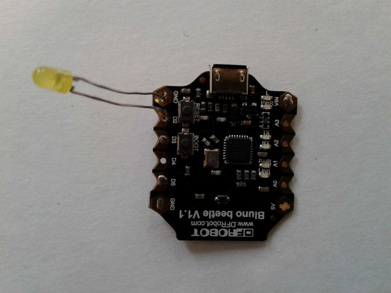
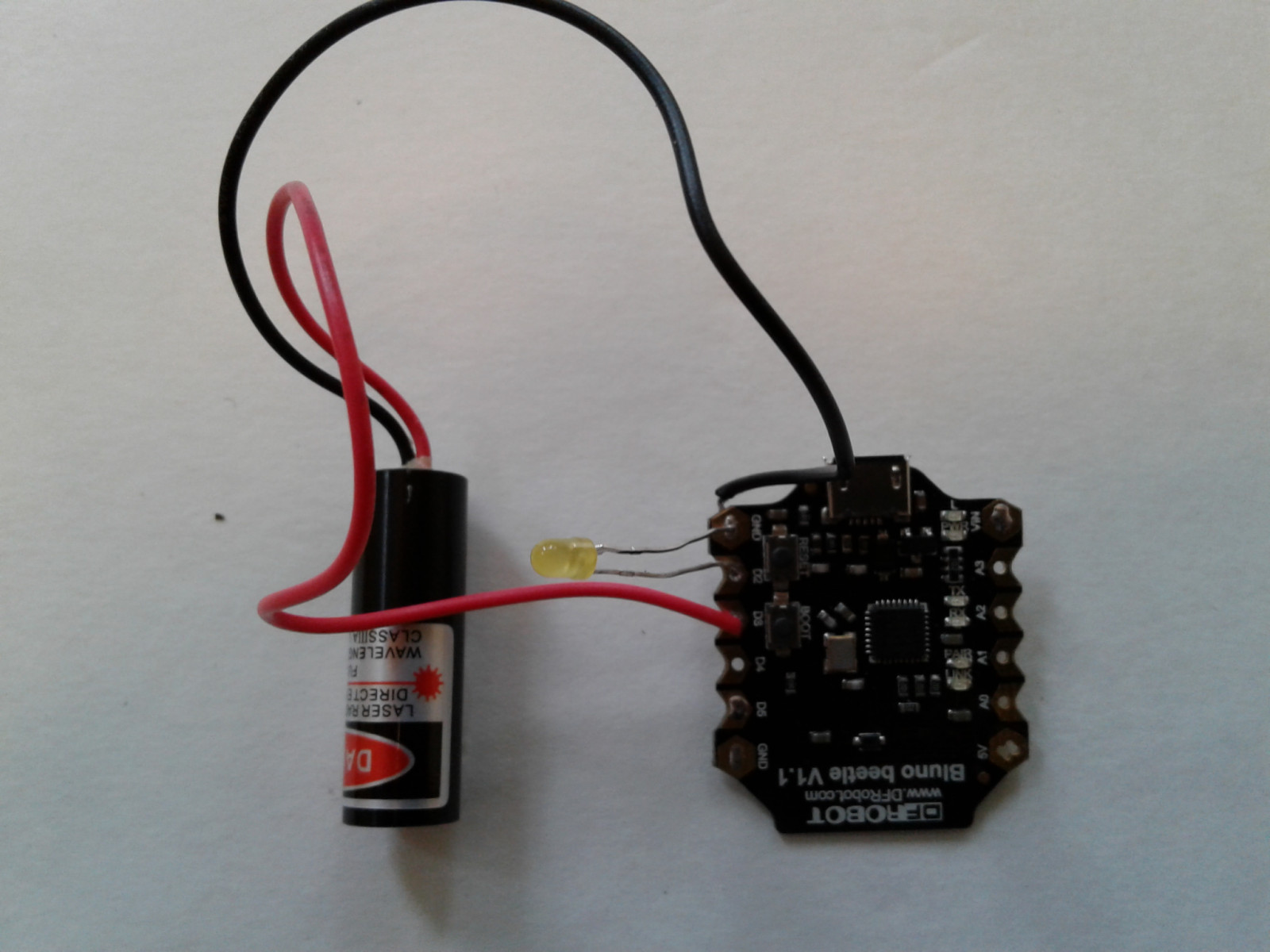
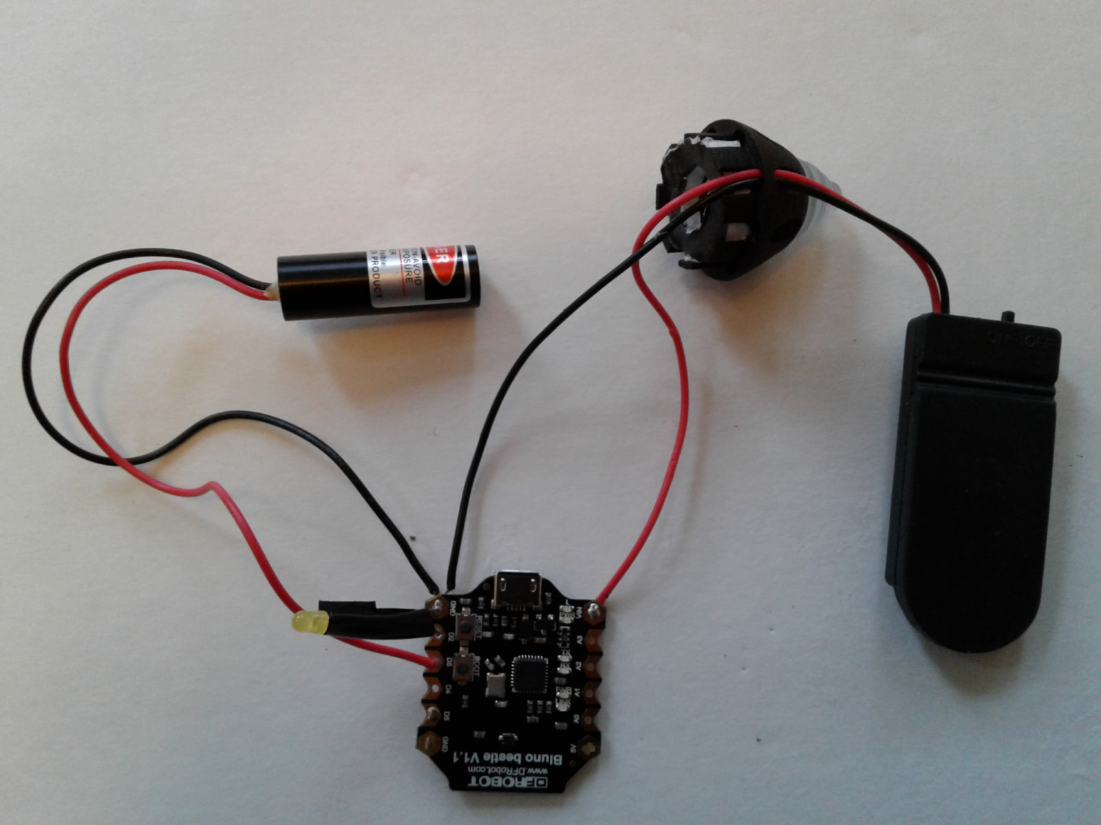
Solder the LED short lead Cathode (-) to the GND pad of the Arduino. Solder the LED long lead Anode (+) to the D2 pad of the Arduino.
Solder the Laser black wire (-) to the GND pad of the Arduino. Solder the Laser red wire (+) to the D3 pad of the Arduino.
Place the wire leads from the Coin Battery Holder through one of the holes in the Model Rocket Nozzle.
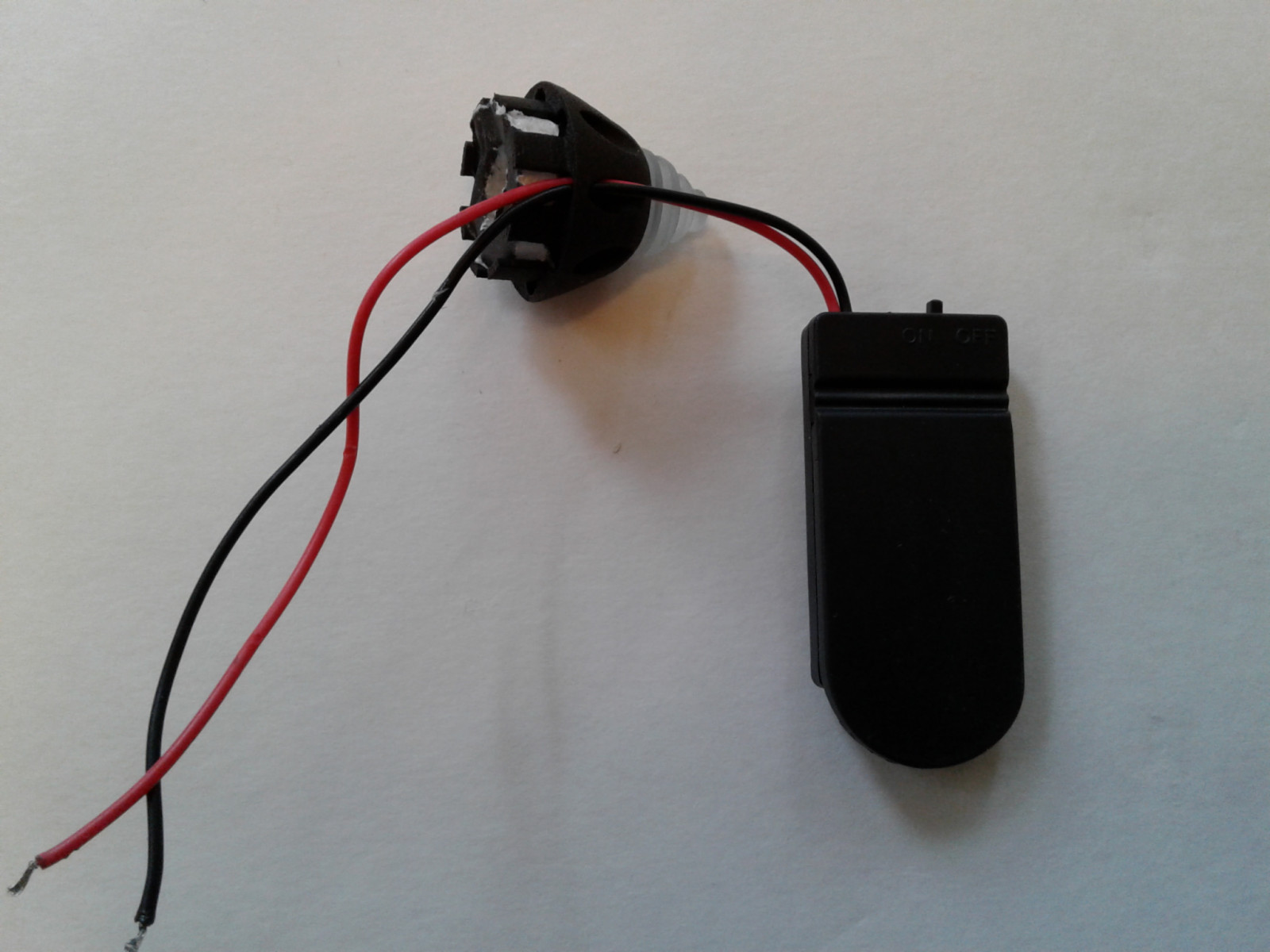
- Solder the Coin Battery Holder black wire (-) to the GND pad of the Arduino. Solder the Coin Battery Holder red wire (+) to the VIN pad of the Arduino.
- Apply electrical tape to insulate the exposed LED leads.
- Install batteries in coin battery holder.
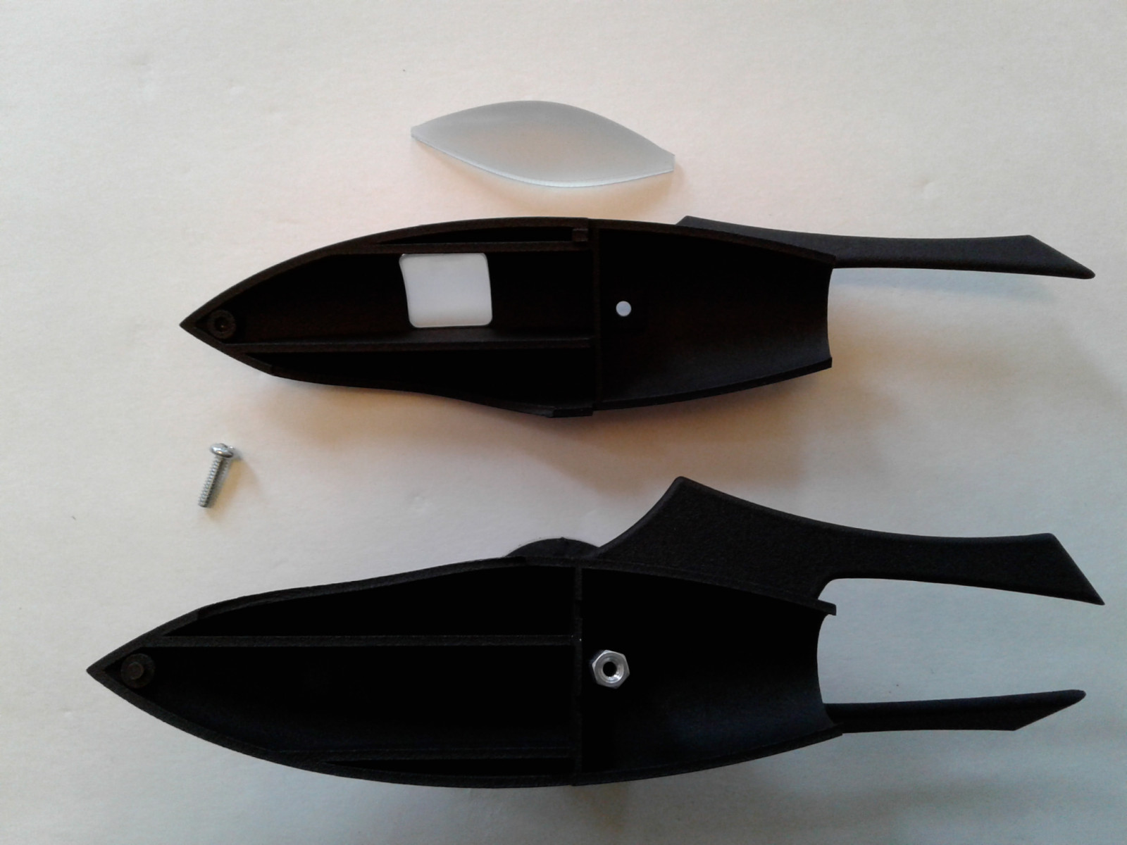
- Remove the screw that holds the two halves of the Rocket Model together.
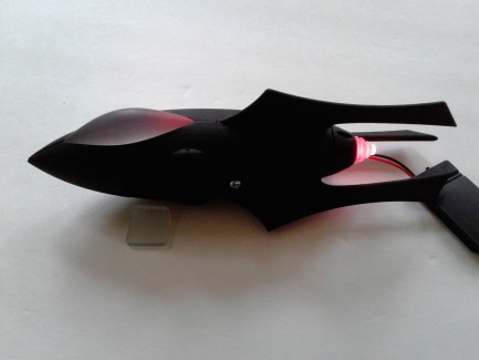
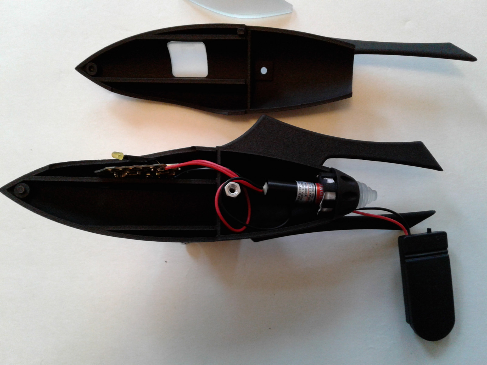
3. Insert the Laser into the hole in the Rocket Nozzle.
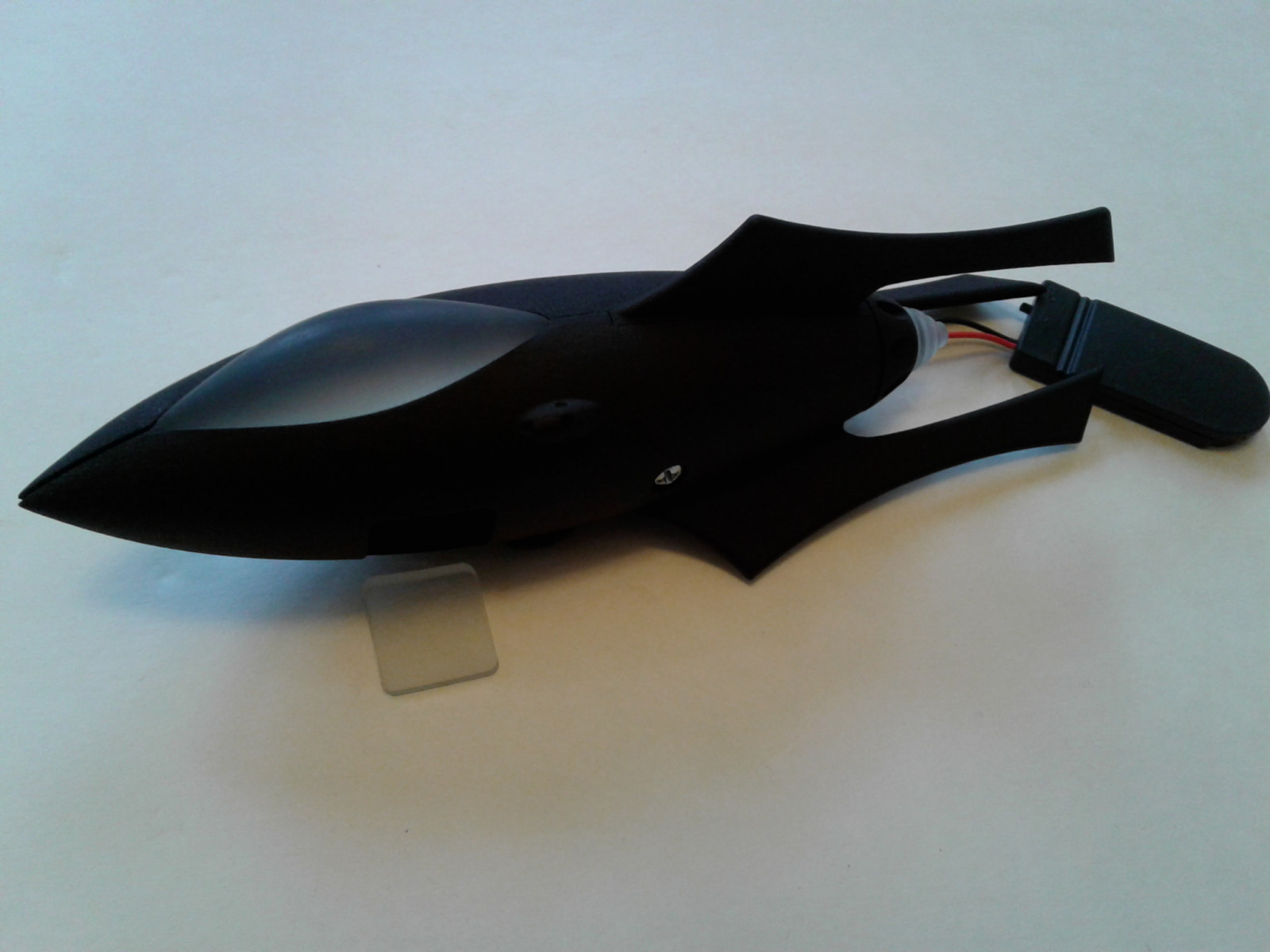
4. Insert the electronic components inside the Starboard half as shown in the picture.
5. Rejoin the two halves of the Rocket Model and screw the two halves together with the screw removed in item 2.
- Turn coin battery holder switch to the on position.
- Power on your Raspberry Pi or any other Bluetooth LE Linux device.
- Turn on the Bluetooth on your device.
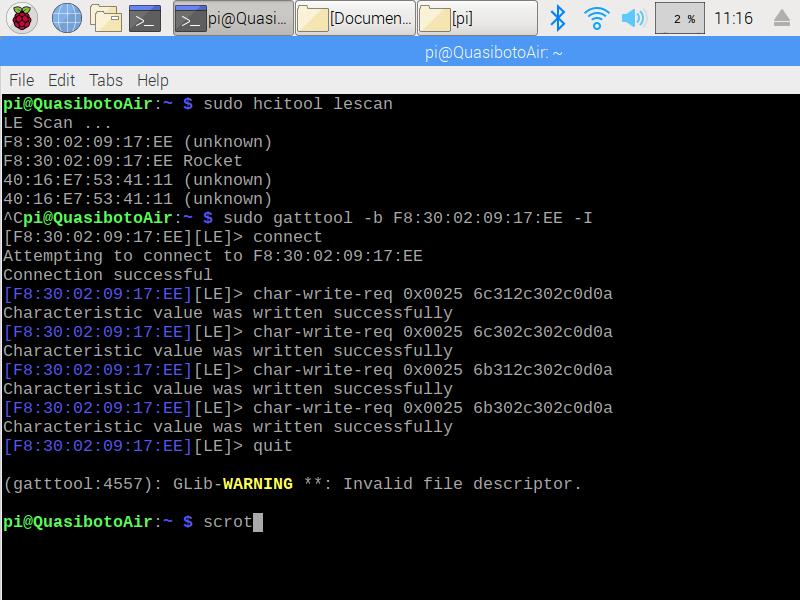
- Open a Terminal and type the following command to scan for the Arduino Bluetooth to determine its MAC address.
- $sudo hcitool lescan
- Run the gatttool using the MAC address found in the previous step. Run the following command:
- $sudo gatttool -b <Device MAC Address goes here> -I (ex. sudo gatttool -b F8:30:02:09:17:EE -I )
- Connect to the Arduino Bluetooth by running the following command at the prompt
- >connect
- Send commands to the Rocket to turn on/off the Laser and cockpit LED
- Turn on output D2 by running the following command at the prompt. This sends the k1,0, string in Hex to the Arduino:
- >char-write-req 0x0025 6b312c302c0d0a
- Turn off output D2 by running the following command at the prompt. This sends the k0,0, string in Hex to the Arduino:
- >char-write-req 0x0025 6b302c302c0d0a
- Turn on output D3 by running the following command at the prompt. This sends the l1,0, string in Hex to the Arduino:
- >char-write-req 0x0025 6c312c302c0d0a
- Turn off output D3 by running the following command at the prompt. This sends the l0,0, string in Hex to the Arduino:
- >char-write-req 0x0025 6c302c302c0d0a