


Blue Beta - Akira
Ok...this is my first ever actual project in electronics, programming and mechanical engineering and i decided to make life difficult from the start by making the entire robot modular so i can update it, evolve it or canabilise it as i see fit.
I've also decided to chart my progress from the beginning so fellow newbies can see the intricaces of learning as you build and see its not as impossible as it feels (assuming i ever get the thing working of course).
Essentially im building an autonomous tank track based, picaxe28x1 controlled, HCSR04 ultrasonic sensor guided obstacle avoider.
(and if your wondering about the Blue Beta name - this is my second attempt at electronics after about a decade and im using as many things i can buy cheap or find lying around the house - including a lot of sticky backed plastic) (but you can call me Dominic)
Attachments:-
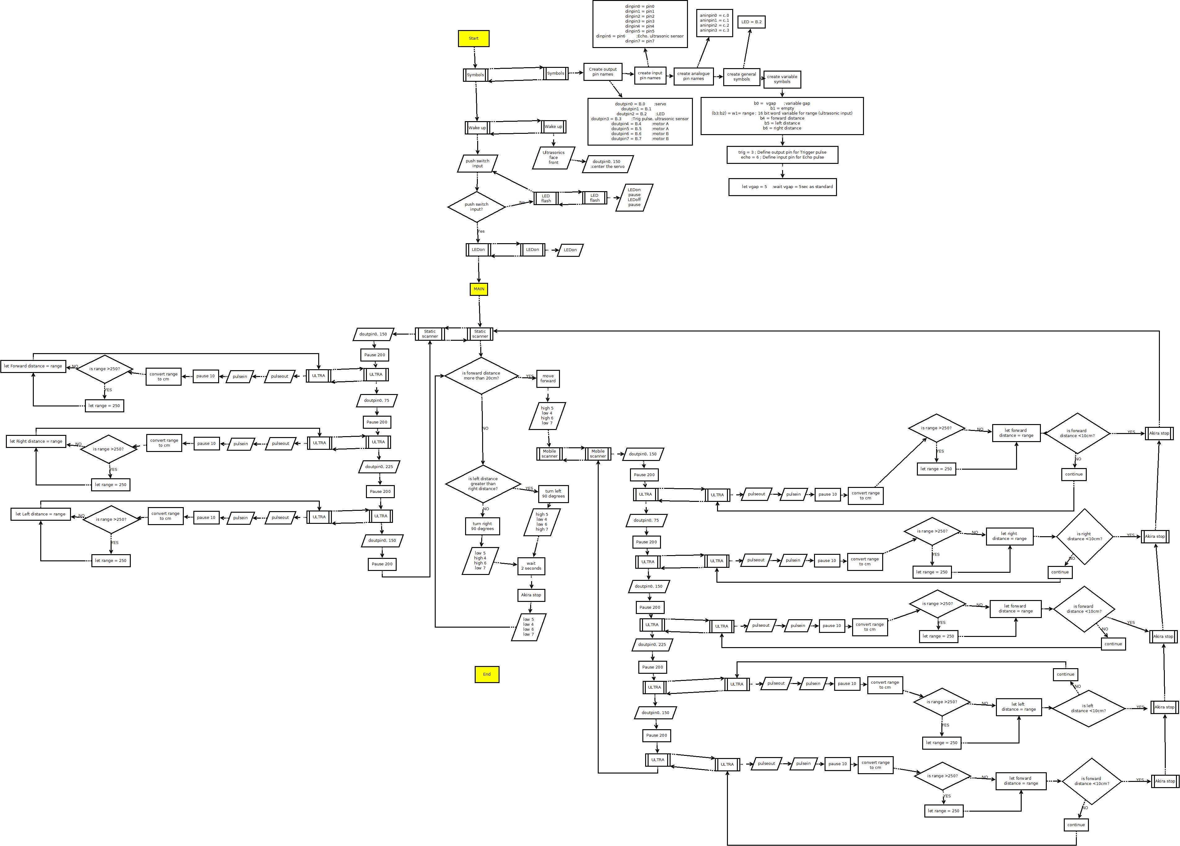
akira final version1.jpeg = flow chart representation of the PBasic picaxe programming
(10 may 12)
so far i have...
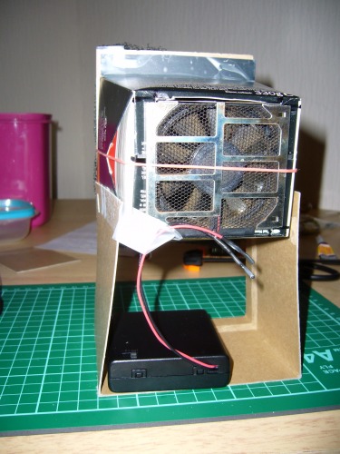
Built a basic (rather weak) solder fume extractor
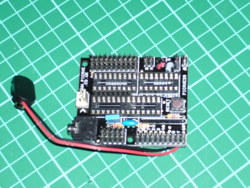
Added extra pins to my picaxe
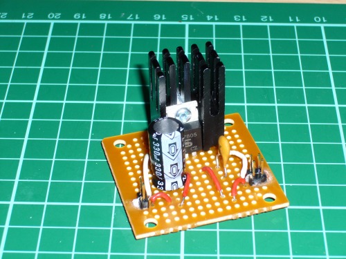
Built a voltage regulator (5v) to remove any problems the ultrasonic sensor might have with fluctuating voltage.
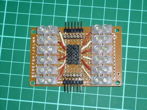
Built a wire to pin converter to allow the use of F/F pre crimped wires between modules.
Built a DIP to pin convertor to allow insertion of extra IC's when required.
All of these were essentially an experiment in soldering as I'd never tried it before - and the main thing i learned was that a cheap soldering iron makes life ten times as hard (and warps the board and melts the glue and melts the plastic base of the pins and...you get the idea)
update (10 may 12)
ok... so a little background...
The solder fume extractor was essentially my first experiment in soldering (i'm sure theres a touch of irony in there somewhere).
i took an old fan from a broken laptop and linked it up to a carbon fish tank filter (useful link) via an unused noodle box then using advice from fritzl's start here page attached the battery box (you know - twist the wires, solder them together and hold in place with heat shrinking tubing). one thing i did learn from this is its best not to use those lighter heated solder strips on free wire unless you fancy burning holes in your trousers in very intimate area's.
Next i moved to the boards - theres an amazing soldering tutorial here (thanks ignoblegnome) which pretty much covered all the bases.
I wanted to create a module which would allow free wires to be temporarily converted to pins, other free wires, single breadboard style component inserts and even a solid multimeter to pin holder via the use of shorting blocks and F/F jumper cables and thus designed my "wire to pin converter". I tried using cut off bits of component wire to connect solder points at first - but ill be honest it turned out to be much simpler just to let solder flow between two points (i use 0.7mm rosin core and it works a treat with the right iron) - one thing i will mention tho... make sure the wire you use is solid core - i started off with stranded at first and after half an hour of trying to get all the strands thru the holes i gave up and just ripped them all out and started over.
I used the old multimeter i had left over from my first attempt at electronics to confirm all the right connections had been made and there were no crossovers but frankly a battery and an LED would have done the trick just as well. One thing i will mention - my multimeter doesnt have a continuity tester per se but you can just as easily use the resistance measure (Ω) which will display "1" when there is no connection and a random multidecimal number when there is.
My second board "DIP to pin converter" i built just in case i fancy adding any IC's to the mix and just popped in one of those easy DIP holders (the longest i could find of the general thin width)
OK... next the voltage regulator.
Chatting to various people on the beginners forum i decided that my best bet would be to build a 5v volt reg module as the HC-SR04 ultrasonic sensor is pretty specific about needing 5v, the picaxe28X1 is happy with 5v and when using the L293D Motor Driver this is reduced down to just under 2.5v which the small motors you get in the tamiya dual motor gearbox like just fine. Thus i would have a super steady voltage and a larger than usual current to cope with any sudden changes in my robots modules.
I used a 1A positive fixed voltage regulator (5v) and linked it up to 6 rechargeable AA batteries giving me 7.2v in and 5v out (rechargable AA's are 1.2v each, standard AA's 1.5v). Now depending what you read some people say the voltage in should be 2v above the volt regs 5v out, others say Vout should be 2/3 of the Vin - frankly tho this worked just fine for me.
technically i could have just left it at this however i wanted the smoothest Vout possible so this is where the capacitors come into it. The idea is to place an electrolytic capacator in front of the volt reg (in parralel - and preferably the right way round) to smooth out any fluctuations in voltage coming from the batteries and a smaller ceramic capacitor after the volt reg (again in parralel and using the same "ground" as everything else - not really caring which way round it goes) to smooth out smaller fluctuations from the volt reg.
At first i spent an age trying to work out the right size of capacitors to put in..studying multiple technical sheets, asking questions in the forum and visiting loads of sites describing thier inner workings and mathematical specificities - i eventually came to the conclusion that it really doesnt matter so long as you pick ones large enough to handle the voltage and small enought that they dont take an age to charge up... so i just picked a random couple that looked nice on camera (electrolytic = 330uf and 25v, ceramic = brown with pretty symbols on it).
And frankly it works a treat (the first time there was a minor fluctuation on the multimeter - but after i set up a more solid connection system...ie not holding everything in place with more fingers than i actually possess... it was fine)
one little extra detail - volt regs dont just make the extra voltage vanish into thin air... well..erm... actually they do. its dispersed as heat which is why A) you shouldnt have too much of a difference between Vin and Vout and B) dont forget to use a heat sink to help the little hot head cool down (i got mine from an old cannibalised 'puter when i was getting parts for the mutant one i'm using right now - together with a lifetime supply of shortening blocks)
next... Picaxe28X1 plus pins
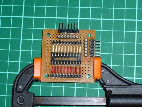
Because im connecting everything using F/F jumper wires i needed to solder in the relevant pins ie - all the extra input and output points picaxe deemed to leave undone. Personally i see this as a good thing as it removes the paranoia a complete beginner might have with altering something so profesionally built (tho i must admit i left it as late as humanly possible so i could perk up my skills on less expensive home made boards).
There is the added point that to link up my ultrasonic sensor i needed to add pins directly next to the main picaxe chip - so frankly i decided to just add all the pins the board would take in one go and hope i didnt bugger the entire thing up. (the HC-SR04 is essentially the same as the SRF05 btw)
Do i really need to mention i removed all the IC chips from the board before starting? (i keep them in a plastic sectioned box with antistatic foam on the base - you know the kind you get for free with certain tech purchases...i certainly aint gonna pay for the stuff - it costs a silly amount of money)
it turned out this was my neatest soldering so far (even under a magnifying glass) so i was very pleased with myself - lets just hope i remain that way when i eventually start plugging things into it. one thing i did spot was how difficult it could be to keep the pins in place and at the right angle - for future reference i may use shortening blocks to keep pin strips parralel and in place and remove them once enough other pins are fixed to prevent heat tranfer (tho i doubt it would be that much of a problem if i did it right).
Update (14 may 12...ish)
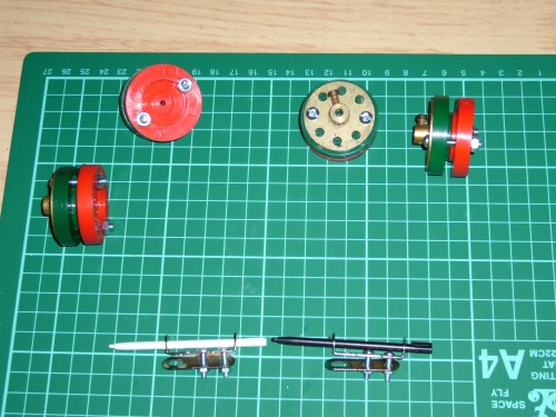
The fact that the wheels for the tracks came in two halves and were supposed to be just pushed onto the axles or glued in place really annoyed me (its not very modular) so I ebayed some screw on meccano wheels, picked up some fake meccano from a cheapo shop and hunted out some bits of plastic as forward axles and created the following...
Update (28 may 12)
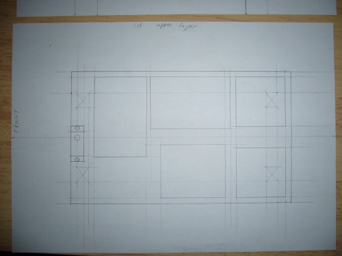
after a slew of minor accidents and injuries (including a head first, six foot fall onto concrete – don’t worry,I’m OK – I bounced) were recovered from, I decided to get back to the project – but to be honest I really wasn’t in the mood for anything computer based (rather long headache) so I decided to allow my old technical drawing skills learned as a teen to resurface from the ashes. The way I saw it, there was a limit to how much designing I could do without having some form of “to scale” model or design to physically work with (CAD packages like inkscape and google sketchup are nice but you spend half your time learning the damn software and there is still a sense of detachment from the physical objects you are trying to arrange), thus out came some paper, a ruler, some scissors and an automatic pencil.
And I was away!
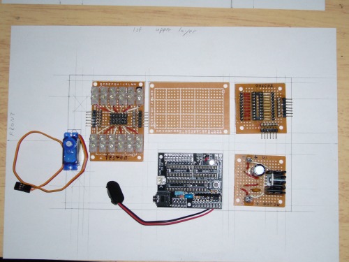
The ability to place the component parts on the paper meant I was able to determine the exact size and shape of the lower and upper plastic bases and see where any problems may arise.
And here’s what I did...
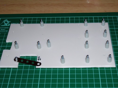
The lower base was designed for support, power and energy. This meant it needed support rods high enough to raise the upper base above both the 6 AA battery pack and the motor gearbox, needed to be wide enough to hold everything without the wheels catching but thin enough that the gearbox axles could reach the wheels, and long enough to stretch out the rubber tracks so they would stay on but not so long that any bump on the floor would hit the base rather than the wheels. I also decided that the front axles should be adjustable so I could alter the tension in the tracks and easily fit them in place.
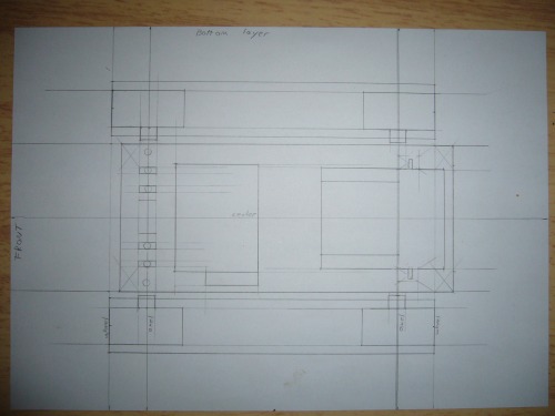
The upper base was designed for control, sensation and adaptability. Thus it needed space for the picaxe28x1, the voltage regulator, the wire to pin adaptor and space for the ultrasonic detector to spin sound, together with the ability to add extra DIP chips or PCB's at a later date. After a while of shuffling round the various boards like I was trying to communicate with an undead ZX spectrum I came to an arrangement where everything worked (with a little tweaking – the unknown PCB might need to be raised slightly higher when its time comes). There’s a good chance I will also cut a hole in that bottom left gap to allow for the passage of wires between levels.
So...the next stage was BUILD SOMETHING!!!
(I always was a bit of a drama queen)
I took the thinnest (cheapest) plastic chopping board I had been able to find in the shops and cut it to size (and learned – don’t use a saw – a Stanley knife {I think its a box cutter for the rest of the planet} is much neater and less thumb threatening – btw the fold out versions are much safer than the old fashion ones with the dodgy blade grip). Next I PVA glued a cut out photocopy of my tech drawings to each piece and used it as a drilling guide.
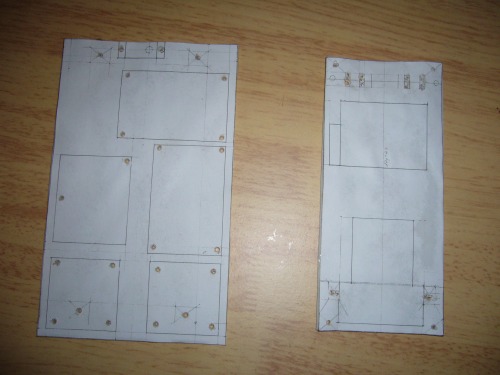
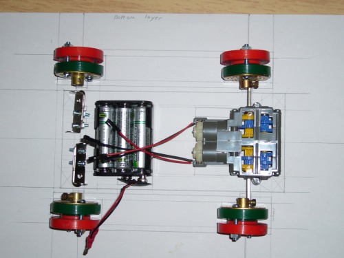
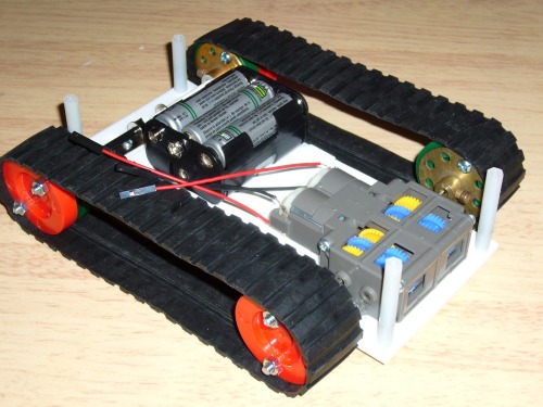
And finally I was able to assemble the lower base of my little “Akira”....
Well almost – it seemed the lower base was at an angle so I had to put in extra support posting to level the upper base out (and allow it to fit) – I also made a border for the battery holder out of that double sided sticky foam to stop it sliding all over the place while still being easy to remove.
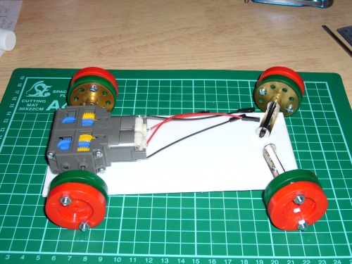
And I ended up with this... stage one complete (feels REALLY good having something vaguely robotic shaped on my desk – I might yet finish this thing)
Now back to the electronics and a bit of programming...
Dom
Update (4 June 12)
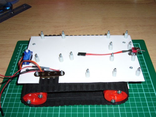
The next stage was cutting out a space for the servo (used to turn the head) and another for the wires to pass between levels. The cheap meccano came in handy again to create a little gate which would both keep the wires away from the tracks but still allow easy access when constantly changing my mind about which wires should go where and why. Next I put in place all the little spacers which would raise the pcb's up while holding them firmly in space (I have never needed the screwdriver function on my drill so much – I’d probably still be at it now with super muscular wrists without it). One thing I did notice was that if I had made the mistake of attaching the pcb's now I wouldn’t have been able to screw in the board to the base level as two of the screws were under pcb's – oops – this is what happens when you try to plot it all out in your head.
So... now ’twas simply a case of screwing on the top level. I slotted in the servo (the axle is dead centre on the board so the hole is cut slightly off centre) and decided to add in a main switch between the batteries and the voltage regulator just so I could leave everything connected rather than constantly unplugging things when I wanted it to stop.
And then I bolted in all the pcb's (I also wired it all up and plugged it into the computer to make sure it didn’t blow up and surprisingly it actually worked – one note tho... the picaxe software despite knowing internally which COM it should be outputting on doesn’t necessarily pick it – so if you get the dreaded “its buggered” in techno speak I’d advise checking that before you burst into tears – anyway wheels turned, I grinned like a Cheshire cat on acid and all was well)
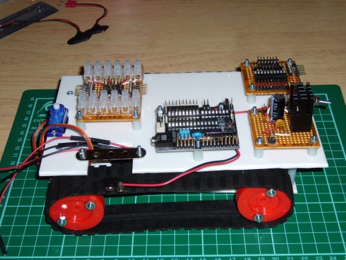
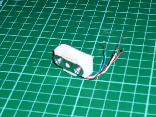
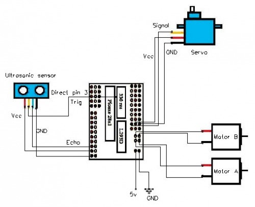
Now came the bit I’d been dreading for an age – how on earth to connect the ultrasonic sensor to the servo and then to the rest of the robot without making a complete mess of things the first time it tuned. The way I saw it I needed a right angle connection for the head to be facing forward, access to the servo arms centre to be able to screw it in place, upward facing output pins (close to the pivoting point) so that the wires would only be a little twisted rather than pulled out of place and a small enough size to prevent it catching on the pcb next to it and to keep the sensor as low as possible so it could see the small objects that still had the ability to get in its way. Simple eh?
I eventually decided on a plastic block usually used in DIY to connect boards at right angles and a 4 pin receiver I’d cannibalised from an old computer. A little trimming on the block allowed it to turn freely and a meccano (damn that stuffs useful) reinforcement bar bolted in place supported the epoxy glue. Now there was just the problem of the wire – it was too thin for my wire strippers to work without cutting it... a moment of inspiration solved that – I could simply char the plastic with a lighter then scratch off the brittle remains with a blunt blade. After a bit of chopping, glueing and bolting all that remained was soldering the wires to the base of the pins and I’d be finished.
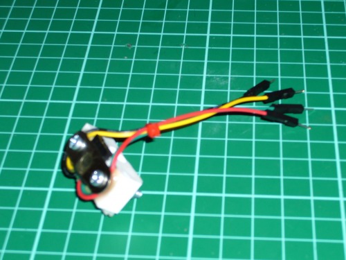
The next hour was another healthy reminder that if you use the wrong kind of wire when soldering you will learn the ability to create obscenities that would make a tomato blush.
Thus I pulled it all to pieces and put four upward facing male/female pin extensions in its place... and now I feel much calmer.
(pics are a bit blurred because my camera has “shiny-thinga-phobia)
Finally it was simply a case of slotting it all together, adding the final wires, posing it in a nice way and creating its official picture.
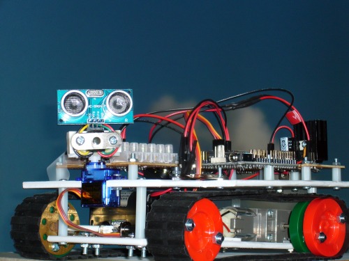
Now all I have to do is learn Pbasic from scratch and program the little bugger.
Dom
Update : 15-06-12
OK I admit I haven’t done any programming the last few days (other things got in the way) but I promised myself I would do something robotic today.
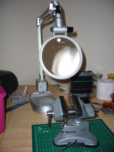
Id bought myself a magnifier on a stand to make my soldering a little easier but it turned out it was way too small to reach over my new vice... a little mechanical engineering was in order. I got an old adjustable lamp stand from a junk shop down the road (only £2) and with a little jiggery pokery created my very own adjustable magnifier for a fraction of the normal price – I’m getting rather good at this technology lark.
Then I decided to create a proper circuit diagram for my robot thinking “Dip Trace” cant be that complicated...right?
After an age spent trying to convert the rather pretty picaxe board picture id built in the pattern editor from one version to another I eventually gave up and just built the various parts in the “paint” program you get in windows then cut/paste them in – its still not too bad for a first attempt – but I sometimes think I’m seriously making life difficult for myself.
If you know a better way of doing it - please let me know (also if you want a copy of the jpegs i made - tho honestly the only difficult one was the picaxe)
Dom
update - 4 jul 12
I decided to start on the programming and thought a good place to start after creating all the basics (again in a modular mode to make finding mistakes much easier) would be converting "time of motor on" into distance travelled or angle turned.
The distance travelled bit worked a treat - i just timed how long it took to travel 2 meters... the angle turned bit - less so.
Basically the grip on the rubber tracks was so great on the smooth floor when the tracks were going in opposite diections instead of the robot turning in a circle it managed to dislodge one wheel, remove the tracks and disconect one axel from the motor gear box - essentially self destucting in such a way to force me to pull it apart to fix it - eeesh.
Ive considered covering the rubber with pva glue to remove its grip - but it doesnt have the greatest grip on the rubber in the first place - we shall see. Of course i have to fix the robot first before i can do a thing...
update - 19 jul 12
Gear box is fixed, wheels reattached, tracks relocated and covered in PVA glue... job done ;)
... and it takes 9 seconds to turn 360 degrees on a smooth fake wooden floor.
This means i can get back to working on the programming ... unless i can think of something else to distract me ...
hmm - now i think on it the wire to pin convertor wasnt built very well due to a cheap soldering iron melting all the plastic and warping the pins...
update - 26 jul 12
first stage of the programming is done - i used DIA flow chart software to build up the shape required by the PBasic later - and frankly its a good job i did - its amazing how much difference a pictoral version of the programming can make - i discovered a whole bunch of mistakes and concepts i hadnt fully developed (reminds me of when i first learned how to use mind maps all those years ago ;) )
the LMR software wont let me upload the actual DIA version so instead ive created a mini and full scale jpeg in case you are interested
update 3 aug 12
When planning out my programming i realised that what i really needed was a touch switch to start akira's movement AFTER the initial power connection - added to this the fact that my wire to pin converter was a bit of a warped mess due to trying to get away with using a seriously cheap soldering iron i decided to reinvent it.
TADA!!
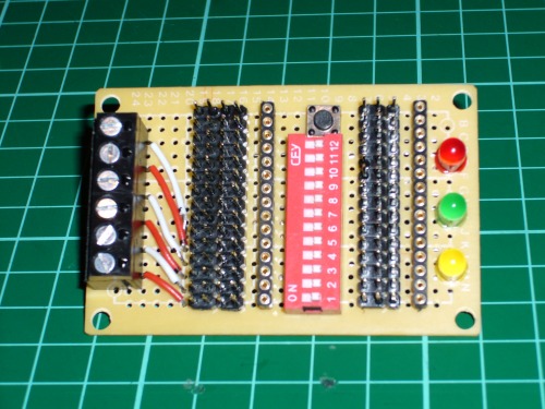
And the next pic shows just how much i need to learn how to make home printed circuit boards...
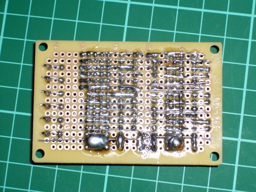
Each of those lines is separate from the next one without missing out a single pin or melting the plastic holding it together ... my head still hurts.
Update 21 – sep – 12
the good news...
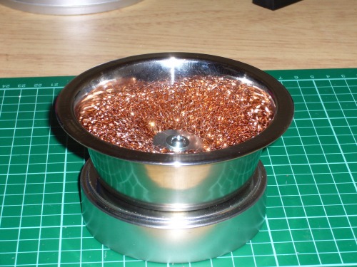
I created a really pretty de-solder pot from a coffee tin lid, a dog bowl, a copper scouring ball and a few nuts and bolts.
The bad news...
well my robot is now officially doing my nut in.
I know this is all a learning experience but I’m really looking forward to the point where I truly understand this programming lark.
As anyone who reads the shout-box or the forums will know I’ve been having problems left right and centre and I’ve decided to summarise and centralise here – if for no-one else’s benefit but my own.
After creating the flowchart I set upon writing the program itself (which obviously required a fair amount of Picaxe basic instruction book reading) and came up with what I thought was a pretty smart conception – its just a pity it didn’t work.
For some reason akira is blind as a bat when it comes to recognising barriers and reacting to them.
Using the debug command I’ve been able to see just what numbers are coming thru from the ultrasonic sensor and make sure they are not being interfered with by the constant forward motion motors or the head turning servo (admittedly – fully charged batteries are a bonus here) but for some reason akira simply wont respond to them – give me time – I WILL sort out the flaw – but for now I’m running in circles.
On the plus side I have learned a few things about programming...
1 - make sure your batteries are recharged after a long night of experimentation or you will get out of character results next time you try
2 – a section at the beginning keeping track of bits, bytes, words, pin uses, allocated names, variables etc. is a life saver
3 – the “DO...LOOP” is a much better way of containing the central program than using “GOTO” left right and centre as you can include “UNTIL” parameters as well and put it inside your “MAIN:...GOTO MAIN” covering everything
4 – making notes all over your program turns it from techno speak into a form of story – very useful when your vision starts to go all blurry after a long night typing (much like now)
5 – start with SERVO to initiate the motor but then switch to SERVOPOS afterwards to prevent it from interfering too much with other stuff
6 – use names for all variables (“SYMBOL”) as its much easier to keep track
7 – OOOHH!! - I think I just spotted why it doesn’t work
8 – be careful with your “GOSUB'S” - you might find out it causes very important sections to be missed out or not reached at the correct time (hint)
9 – make sure you get at least some sleep – AND RECHARGE YOUR BATTERIES!
wander around the room not hitting things
- Actuators / output devices: tamiya dual motor gearbox
- CPU: Picaxe 28x1
- Power source: 7.2v 6AA rechargeables leading to 5v voltage regulator
- Programming language: Picaxe basic
- Sensors / input devices: HC-SR04 Ultra Sound
- Target environment: indoors