


Biribot
Simple Biribot "avoiding obstacles" program
Biribot_walk01 is a simple program, completely documented. Biribot_walk02 is a more elaborated, version with an improved estrategy
To summarize,the most used and simple way to design an avoiding obstacle "walk" program is
#define TIME_A 500
#define TIME_B 1000
#define MIN_DISTANCE 10.0
float Read_position(); // Prototype
..................
void loop()
{
float pos;
Move(FORWARD);
do
{
pos = Read_Positicion();
} while( pos< MIN_DISTANCE );
// Do something, for example
Move(REVERSE);
delay( TIME_A );
Turn( LEFT );
DELAY( TIME_B );
}
we won't be awarded for a program like this, yet it works!
I have tried to give a bit of "roll", or "swing" to Biri's program, as you can see in the video. Biri tries to find out the normal direction to an obstacle, then he gets closer to it slowly, moves backwards and turns right for a second
The main disadvantage of Biri is the fact that he is an open loop system, This means that we don't have any way of feedback to guarantee that the systems gets the state we tried to command. For example we would like to tell Biri something like
int angle = 45; //To rotate 45 degrees
..............
Turn( LEFT, angle );
but we need some kind of response (feedback) from Biri to know the actual degree he has rotated, so we should implement an angle-sensor. Another simple reason to implement a feedback line in Biribot's circuit is a command like
Move(FORWARD);
Biri will start both servos to go forward, but surely they wont move the same speed ( due to friction forces on wheels, gears, different internal coils in each motor ..) and Biri will desviate left or right on his way. We may tune Biri to move forward adding/substracting an offset to one motor, i.e
move( letfmotor , speed);
move( rightmotor , speed - OFFSET );
with OFFSET a constant to be defined empirically. But the question now is... Will be OFFSET the same for the whole range of speed? In other words, if we tune the value of OFFSET (i.e. 23 ) for speed = 40, we can't guarantee that this value will be fine for a new speed of 70, and Biri should move straightforward for speed = 40, but not at a speed = 70. If we go one step ahead, we could calibrate different pairs [ OFFSET , speed ] and store them in EEPROM ( We have 1Kbyte in our ATMEGA328P ) to load later the one according to Biri's selected speed, but this is artificial
Finally, and open loop system is controlled mainly in two different ways, that is
- Using well calibrated subsystems and
- Using time based subprocesses adjusting each one
As a result, we could code
#define 15_DEGREES_DELAY 250 // Values are invented
#define 30_DEGREES_DELAY 475
#define 45_DEGREES_DELAY 700
#define 90_DEGREES_DELAY 1250
Turn( LEFT );
delay( 45_DEGREES_DELAY );
to turn Biri the desired angle
Josele
Simple library to move Biribot
Here you are a simple video showing the basis to move Biribot. Attached is the code, very simple and ( I hope ) clear.
To simplify, we have two similar low level functions, which control both motors, called lm_move() and rm_move(). Here we have the code ( nothing new ). Note that speed is added/ substracted to the center position of each servo, as long as both motors move in opposite directions
/*
lm_move()
Move Left Motor
pars:
where: { FORWARD , REVERSE , STOP }
speed : { 0 , V_MAX }
*/
void lm_move( int where , int speed )
{
if( (speed > V_MAX) || (speed < V_MIN) )
return;
switch( where )
{
case FORWARD:
lm.write(LM_CENTER+speed);
break;
case REVERSE:
lm.write(LM_CENTER-speed);
break;
case STOP:
default:
lm.write(LM_CENTER);
}
}
/*
rm_move()
Move Right Motor
pars:
where: { FORWARD , REVERSE , STOP }
speed : { 0 , V_MAX }
*/
void rm_move( int where , int speed )
{
if( (speed > V_MAX) || (speed < V_MIN) )
return;
switch( where )
{
case FORWARD:
rm.write(RM_CENTER-speed);
break;
case REVERSE:
rm.write(RM_CENTER+speed);
break;
case STOP:
default:
rm.write(RM_CENTER);
}
}
Now is simple to code functions like Move(), Rotate() or Turn(). We can find them in the attached file Drivetrain_test.zip. For example, the code for Turn() - that moves only one motor - is
/*
Turn()
Turn Biribot moving only one motor FORWARD/REVERSE
pars:
where: { LEFT_FW , LEFT_RV , RIGHT_FW , RIGHT_RV } ( FW: FORWARD , RV: REVERSE )
speed : { 0 , V_MAX }
*/
void Turn( int where , int speed )
{
switch( where )
{
case LEFT_FW:
lm_move( FORWARD , speed);
rm_move( STOP , speed);
break;
case LEFT_RV:
lm_move( REVERSE , speed);
rm_move( STOP , speed);
break;
case RIGHT_FW:
lm_move( STOP , speed);
rm_move( FORWARD , speed);
break;
case RIGHT_RV:
lm_move( STOP , speed);
rm_move( REVERSE , speed);
break;
default:
return;
}
}
Finally, we have extra functions like Engine_start(), that attaches both servos, Engine_stop() -detaches - or Neutral(), that moves both servos to their central position. This last function will be used frequently, since each call to lm_move()/rm_move() start a servo continuosly in time
In our next steps we will a simple loop for Biribot to run and avoid obstacles not the standard and easy way. Then, we will give feedback to Biribot, which is now an open loop control system. And ( why not ? ) we will add some IR "home made" sensors to Biri
Modifying the servos
The original Biribot used a L293N to drive the servos. I have to admit that I didn't know the recipe that Ossippee gave to me. Here you have the link
https://www.robotshop.com/letsmakerobots/how-modify-micro-servo-continuous-rotation
The code in the link was a bit strange to me, as long as I'm not expert in Picaxe ( To be honest I don't know a word haha! ). So I went to an example in Arduino IDE, that is sweep...
The standard code in Arduino for a servo is
#include <Servo.h>
................
Servo myservo; // create servo object to control a servo
................
void loop()
{
for(pos = 0; pos <= 180; pos += 1)
{
myservo.write(pos);
delay(15);
}
}
So we should expect the servo to stop if we code
myservo.write(90);
This is nearly true. In fact I had to adjust my servos to 84 and 87 to stop completely the gears ( no sound, no move ). Then we can use PWM and write() to move the motors. So,
myservo.write(80); moves the servo one way, slowly, and
myservo.write(0); moves it the same way, faster. And
myservo.write(95); moves slowly the servo the other way, and
myservo.write(180); moves the servo the maximun speed
Here you have a simple program, that is the skeleton of my code
/*
Servo test
Hardware: Connect a modiffied servo to pin 10
Notes: to get the exact number for CENTER ( in my servo was 84 )
a) Remove the first PAUSE_2;
b) Type FOREVER;
c) Starting with 90, try different numbers until the servo is totally stopped
d) Then, rechange FOREVER; with PAUSE_2;
*/
#define FOREVER for(;;)
#define PAUSE_2 delay(2000)
#define SERVO_PIN 10
#define CENTER 84 //The position that gets stopped. It should be 90
#define V_ACT 50 // Simple speed to test the servo
#include <Servo.h>
Servo myservo;
void setup()
{
myservo.attach(SERVO_PIN); // attaches the servo on pin 9 to the servo object
}
void loop()
{
// Go neutral position
myservo.write(CENTER);
PAUSE_2;
//Move one direction
myservo.write(CENTER - V_ACT);
PAUSE_2;
// Go neutral position
myservo.write(CENTER);
PAUSE_2;
//Move opposite direction
myservo.write(CENTER + V_ACT);
PAUSE_2;
}
With this in mind we are ready to build a basic library of functions for Biribot to ...
- Move
- Turn
- Rotate
- Change direction
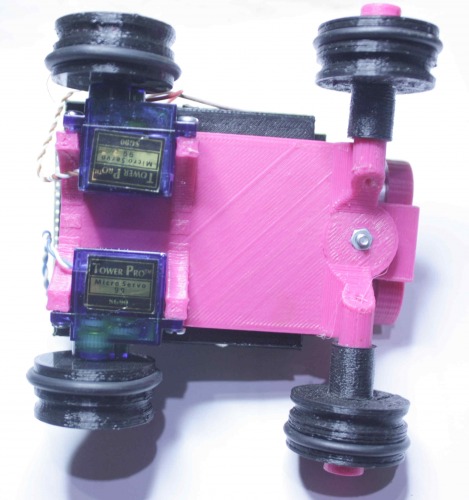
Assembling Biribot
Biribot is very easy to assemble. You only need some cyanoacrylate glue ( Loctite, Super Glue 3 ) for the front arms and battery pack.
I have redesigned the front arms to be printed in two parts instead of one, and the results are better. Here you may see it
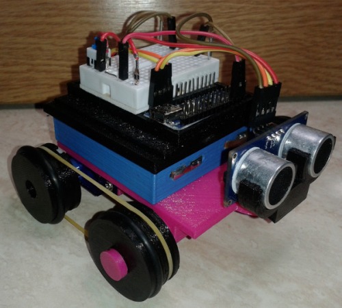
You can see a rubber band connecting both wheels to simulate chains. You can connect them with 2 bands, or just one and use rubber rings for a better friction.
You can also see a mini breadboard with the HC-SR04 ultrasonic sensor and servos connected.
Biribot design
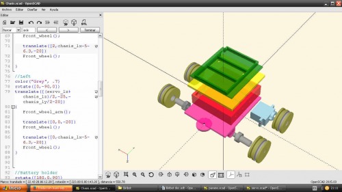
Full view of Biribot in OpenScad
I have uploaded all the files to print Biribot. You may find both .stl and .scad files. I have to translate some file (I think one .scad), cause the originals were made in my mother tongue, Spanish ( next I will do it in English haha ! )
Notes:
a) You may see something like this at the beguinning of most of files
//To test the module uncomment the next line
//Rear_wheel2();
so its easy to render the files, just deleting the 2 slashes ("/") and pressing F5. Have fun!
b) In params.scad there is a variable, called resolution ( the last one in the file), involved in each cylinder() function, i.e.
cylinder(r=fr_wheel_diam/2,h=fr_height,$fn=resolution);
you may set it to resolution = 50; instead of its original value (resolution = 100) to speed up rendering.
c) One extra advice. Take care to render full_view.scad. It will take a long time to render. This file ( the picture above ) is just to see all the pieces together, to "dance" around Biribot. I think the result is nice, and it took me more than a while hehe!
d) I will add a readme.txt file, but Im think everything is simple
Well, it's ok now. I have tasks to be done, like videos ( I will stay at my mum's a few days), but I wanted to finish the design. Step by step. Now I can check the CR servos and go with schematics, and all that stuff.
Note: There is one file, "Sonar_mount_double.zip", with the original mount for the HCSR04 sensor, in the Rover mentioned below. It is not difficult to design, but I wanted to have at least a piece of it. It is appart from Printfiles.zip
Intro
This is Biribot, my first and very simple robot
The name "Biri" comes from an old Seville Futbol Club player, called "Biri biri" ( He was from Gambia ). I am a Seville supporter, so all my robots are dedicated to players in that team.
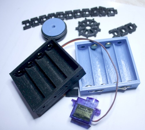
Drive train... servos Battery holder, wheels and chains
Parts:
- Chassis designed with OpenScad
- Wheels designed with OpenScad
- Wheels can be changed by chains.
- Wheels may be conected using rubber chains.
- Battery holder: modified from the Parameterized Battery pack with electrical connections, by Juan Gonzalez-Gomez (Obijuan) [email protected]( https://github.com/Obijuan/Miniskybot ). The design is derived from the Battery comparment generator, (c) Nikolaus Gradwohl (guru (at) local-guru.net) http://www.thingiverse.com/thing:5051 )
- Motors: TowerPro 9g servos modified for continuous rotation ( https://www.robotshop.com/letsmakerobots/how-modify-micro-servo-continuous-rotation ). I have to test it, to remove the original L298N driver ( Txs ossipee )
- L298N to control servos
- Ultrasonic sensor HC-SR04
- Arduino ProMini or Arduino nano
Hardware costs: Less than 15 euros
History:
When I got my Prusa Hephestos I wanted to start my projects "at the drop of a hat" ( Bob Dylan should say ), but I realized that everything was new to me, so I needed to calm, going step by step.
I was working in another project with Arduino and VUSB and I found this "Rover" made with an ATTiny, called ProTrinket
( https://learn.adafruit.com/trinket-powered-rover )
I realized that my first project should be something like the Rover, but I didn't want to download the project and print it out to make my first robot.
My main aim was to design a simple, cheap robot, to show my students a simple project.
I use OpenScad, and soon I could design the chassis, and the front wheels. I tried to make modular arms for the wheels, in order to be printed in an easy and secure way. So I designed a chassis with holes to fit arms ( cylinders ) for the front wheels in.
For back wheels I designed the horn to be a “negative” in the wheels, to use the nylon horns provided wth the servo
Searching here and there in Internet I found a battery holder, ready to be modified, adding metal clips, so the body was finished! A simple tap to fit a L298N Driver for the motors ( cheap TowerPro servos modified for continuous rotation ) in a H bridge, and the Arduino board was easyto design and print.