


Big Guy (WIP)
Based on a ZipZap micro R/C car with a custom PCB and Pic16F88, this "Big Guy" is the start of my new, microbot. I've wanted to build a small robot for some time. I also wanted to play with front wheel steering. About ten years ago, I came across these tiny R/C cars at the local Radio Shack. They were the size of MatchBox cars. I bought two and had a ton of fun with them. Eventually, one stopped working and the other lost its controller in a move. I put what was left in my parts salvage box and forgot about them.
Not long ago, I pulled one out and gutted it. The rear wheels are driven by a single small DC motor. The motor itself can be swapped along with the drive gears for different arrangements of speed and torque. The front steering is controlled by two electro-magnets. This is the first version of the ZipZap, so the steering is not proportional. The steering wires themselves are magnet wires, with some kind of enamel coating on them. With a bit of work, I was able to expose the wire and get them soldered to some USB wire. I hot glued the heck out of them and sealed the whole ugly mess with "Ticky Tack" poster putty. Thats the blue blob on the side.
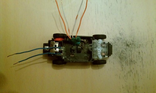
I found a small LiPo from one of those keychain LCD picture frames that was the same dimensions. Then, it was off to make a board.
For the board, I tried some new things. First, I made my own PCB. I've only done 3 or 4 other boards, so I'm still getting used to the process. I use pre-treated, single sided, photosensitive boards. The traces come out really well. For etching, I use vinegar, hydrogen peroxide, and salt. It's a weak acid, and it takes a while to etch. I have young kids, so I don't like keeping strong acids in the house. This mixture is cheap, and I can just mix it up on the fly as needed. The other new thing about this board was the microcontroller form factor. I decided to try to hand solder an SOIC version of the Pic16F88. The down side is that the board is single sided, and I didn't have any SMD headers. This meant that everything but the microcontroller had to be soldered on the same side as the components. This ended up being easier than I thought. Soldering the SOIC part was easy. I used a lot of flux on the traces. Even soldering the headers on the "wrong" side didn't prove to be too difficult. Here's the result:
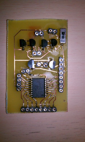
There was one tiny problem with the board. I tested every pin to point, but somehow, I missed the fact that a bridge had formed between Vcc and ground. "Puff!" My first ever sighting of magic blue smoke. One of the transistors gave up its humble spirit for my soldering error. Before I could kill the power, an electrical arc and a "Pop!" The Vcc trace split and popped up from the board. I found the bridge and cleaned it up. I fixed the Vcc trace. The transistor still worked! I couldn't believe it. We'll see how long it lasts. With those trials out of the way, I moved on to put the base together.
I put the battery on top of the chassis and secured it temporarily with electrical tape. I affixed the board on top of that, again with tape for now. Here is the result:
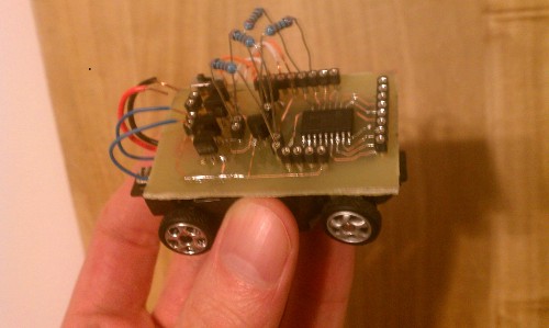
How 'bout them ugly resistors? Okay, I can't just make a board for one purpose. I designed the board with all pins of the Pic broken out. It has two transistors to drive the left and right steering and a full H-bridge for the motor. I used pins to keep these separated from the microcontroller's pins. I'll cut the resistors down at some point. Here's an ugly shot from the side:
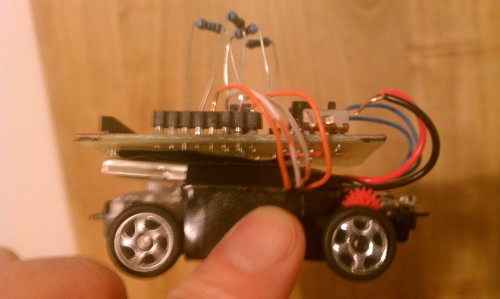
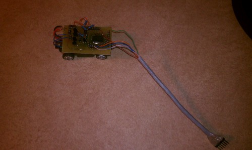
Next up was to program the microcontroller. I tested it after fixing the short and it still worked. The trouble with this board is that I didn't have room for an ICSP connector. I made a makeshift cable. I still need to color code the header pins to fool proof the connections. Here is a picture of the cable hooked to the board:
All this work was enough for one evening. I still need to fashion the front sensor board and slap some code in. I plan to make a little board with three IR LEDs/phototransistors to look straight ahead as well as left and right 45 degrees. I want it mounted perpendicular to the ground on the front like an odd looking set of headlights. I'll probably add a bump sensor to the back. I'd like to swap this out for a line sensor too at some point.
That's all for now. It felt good to work on a robot again!
Update 26 Jan. 2013:
I decided to go ahead an make some headlight/eyes from parts I had lying around. I cut some proto board down to 13 holes wide by 11 holes tall. Using Oddbot's schematic for distance sensing IR emitter/detectors ( the original one ), I laid out this board:
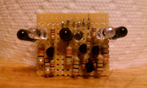
When tested, everything worked, but the center eye was not very sensitive at all. It only gave readings from 102 to 108. I added some shrink wrap around the emitter, and the reading started to match the sensitivity of the left and right eyes. All the breadboard testing was done at 5V, so it will need some work to figure out how it performs at 3.7V on the robot. Notice the big, chunky 1/2 Watt resistors? Like I said, I used what I had lying around. It sure made for some layout fun!
Here are some shots to show the eyes hooked to the chassis as well as a shot for perspective.
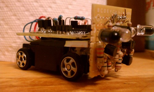
a 3/4 shot at frog's eye view.
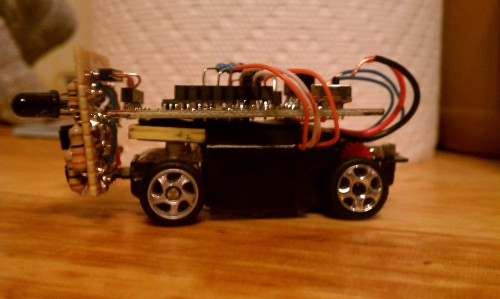
side view from the other side.

from the top.
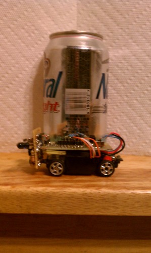
a little perspective, next to a cheap 12 oz. beverage.
Next up will be some test code to find the ranges of the eyes when hooked in to 3.7V. Once I have those, I can finally get some movement code and shoot a video. It's coming, I promise! Robot time has been at a premium lately. Thanks for checking in!
Update 3 Feb., 2013:
Good News: After a series of mechanical failures with my bench equipment, I managed to test the Big Guy's eyes at 3.3V. The left eye wasn't doing well. I added a heat shrink sleeve to the left eye, and it now reports in the same range as the others. Mysteriously, the right eye works fine without a sleeve, but it works miserably with one. I'm leaving it off for now.
Bad news: I finished writing the initial test code for the Big Guy. The code makes him a simple obstacle avoider. It runs beautifully on the breadboard, but... When I loaded it on the 'bot, he refused to engage the motor. I bit of probing around makes me believe that both of the PNP transistors in my simple H bridge are shot. The driver will work with positive applied to either half of the bridge through the resistor, but only if I have the ground attached to the other pole either directly or with no resistor on the base of the PNP. Apparently, that magic blue smoke I saw actually meant they had died. They were working up until now, but I feel they have gated their last milliamp.
Unfortunately, they are going to be a royal pain to desolder. They are soldered on the component side, and several components block easy access. I'll have to desolder at least three of the transistors. I'm worried about ruining the traces, too.
So, the Big Guy will remain a Little Brick until at least after the SuperBowl.
Stops shorting out! ( will explore, line follow, etc )
- Actuators / output devices: 1 tiny DC motor and front, two wheel steering
- Control method: autonomous
- CPU: PIC16F88
- Operating system: Programmed on Linux
- Power source: 3.7v LiPo
- Programming language: Pic Assembly
- Sensors / input devices: Bump switch, will have IR detector/emitter pairs, and later line sensing
- Target environment: indoor, smooth flat surface