


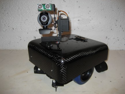
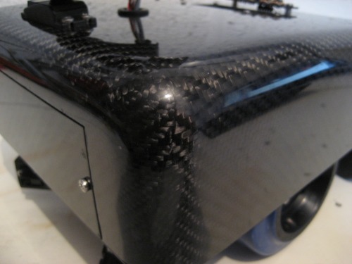
BFRMR1 with custom carbon fibre shell
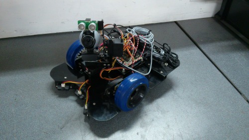
This is my latest robot project which I have named BFRMR1. It is a differential drive robot with two castors at the rear. The chassis is made from aluminium sheet with all brackets and mounting plates also made out of aluminium. The picture below shows all of the aluminium pieces cut and ready for painting.
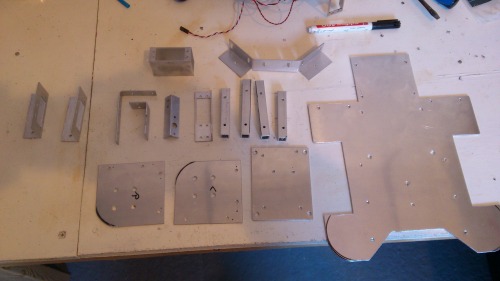
I painted all of the parts black using spray paint which ended up looking pretty good.
The wheels for this robot are 100mm diameter rubbered wheels, the type intended for large trolleys, usually mounted to a castor bracket. They came with roller bearings which were removed and the hub machined flat so that a servo horn could be bolted to the wheel for attaching to a servo.
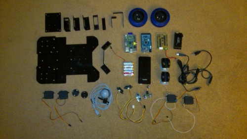
The picture below shows all of the parts of the robot (minus the encoders which I forgot to put in the picture) layed out ready to be assembled.
This robot uses two modified, metal geared servos to power the drive wheels. The two rear cators are the type intended to mount on furnature, which work really well when driving on carpetted floors.
The pan/tilt assembly at the front of the robot used two servos to which I attached an additional wire to the internal potentiometer for some crude feedback of servo position. My last project used external pots to sense servo position which was much more accurate but I was willing to sacrifice accuracy for simplicity in this project. A webcam and sonar sensor are attached to the pan/tilt arrangement.
I also have 3 sharp IR sensors mounted to the front of the robot to detect obstacles that are low down on the floor. Two custom IR encoders read a patterned disc mounted to the wheel to give speed feedback to control wheel speed.
For control of the robot I am using an Arduino mega with a custom shield attached that breaks out the analogue pins, the pwm pins and a bunch of digital pins. This board also has a relay on it to switch servo power on and off via the arduino. I'm also using a Raspberry Pi which communicates with the arduino via the usb connection. The Arduino is handling all of the reading of the sensors and controlling of the servos. The pi is handling the higher level control.
For power I have a 6V battery pack to power the servos and a 12000mAh USB battery pack to power the pi, a usb hub and the Arduino, which should give me many hours of running time.
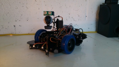
A few more pictures of the completed robot.
The software for this robot, as with most projects, is a work in progress. The code running on the Arduino runs control loops for the wheels and the pan/tilt servos whilst waiting for a packet of data to be sent to it. This packet contains wheel speed and servo position setpoints. When a packet is recieved, the setpoints for the control loops are updated, the sensors are all read and a data packet is sent back to the pi containing sensor values and encoder counts. The software on the pi, written in python, generates a GUI displaying all sensor values with sliders to control wheel speeds and servo positions manually. It periodically sends a data packet to the Arduino and recieves a packet back, the contents of which it uses to update the GUI.
Update 21/11/14
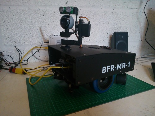
My robot BFRMR1 has gone through a few design iterations since this was first posted. I realised that my initial design did not allow me to easily enclose all of the electronics and so I redesigned the base plate to allow an aluminium shell to be fitted to the robot. The pan/tilt unit for the camera and sonar sensor were mounted to the top of the shell along with a TFT screen and some tactile switches. These were connected to the raspberry pi to allow the robot to be controlled without connecting to another pc. This version of the robot is shown below.
This design worked well and provided more protection for the electronics inside the robot. However, this version of the robot did not last long as a friend of mine who has been perfecting his skills with carbon fibre mentioned making a custom shell for the robot. This was an offer I couldn't refuse! I made a pattern using styrofoam and shaped it to the shape I required. I gave this pattern to my friend who spent a lot of time coating and sanding the pattern ready to make a mould for the part. He made a mould and then made the carbon fibre shell for me.
I had to trim the shell to size and cut openings for the head servo, TFT screen and an access panel at the front and rear. I had to dismantle the robot to modify the base plate to suit the rounded corners of the shell. I made brackets to mount the shell to the robot which were attached to the shell using epoxy resin. The head servo, TFT screen and switch array were fitted to the shell and then attached to the now rebuilt robot base. I am very pleased with the finished product.
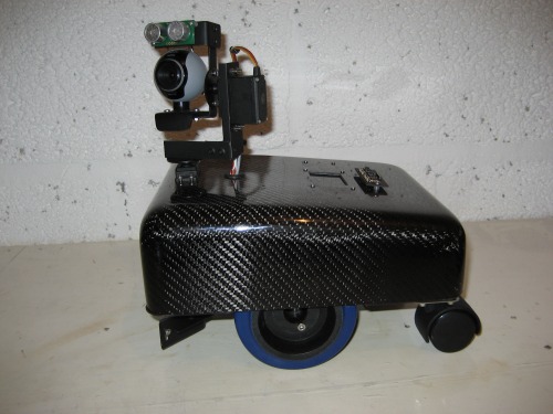
The robot looks good and the carbon fibre shell only weighs 260g compared to 750g for the aluminium shell. Some more pictures of the robot below.
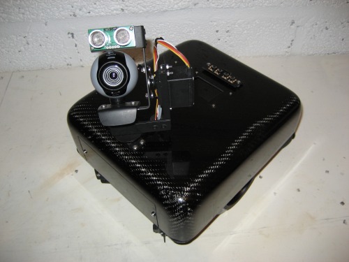
The screen is an adafruit 2.2" TFT display and I am using it to select between various modes of operation. The tactile switch array and the screen interface directly to the Raspberry pi GPIO.
Update 9/12/14
Video added of robot showing some test moves and doing basic obstacle avoidance. The video also shows the robot finding an object of a certain colour and driving towards it. As always the software is a work in progress but you can find the current code on github here.
Update 18/12/14
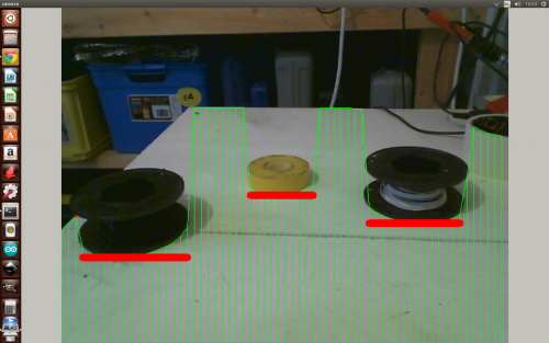
I have been working on detecting obstacles on the floor in front of the robot using the camera. I have made some progress so I made a short video of it in action. I can now get screen coordinates of the edges of obstacles in front of the robot which I am hoping to use to make a kind of map to aid in path planning to get to a target. Check out the picture below of the robot detecting obstacles whilst sat on the workbench.
Update 24/4/15
I have added a new video of my robot navigating to a target using vision and OpenCV.
More details can be found on my blog at www.bigfacerobotics.com
Obstacle avoidance and colour tracking using sonar, IR sensors and a webcam