


BEDA 4 – my first line follower
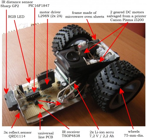
This is my first MCU-based line-follower, which I made for the Robotic Day competition in Prague this year. As usually, the robot performed much better at home than at the competition J. The main problem was sharper angles on the track than I expected and trained for. Maybe you can give me some advice how to deal with it best. Also the Sharp GP2 IR distance sensor got blinded by a direct sunshine on the track, so I will have to replace it with an ultrasonic sensor for the next model BEDA 5.
The mechanical parts:
- A frame made of steel sheets from a microwave oven
- 2 geared DC motors salvaged from a printer Canon Pixma i5200 (they also have rotary encoders that I plan to use in the next model)
- rubber wheels from a RC car, 75 mm in diameter
- cut ping-pong ball as a front wheel
The electrical parts:
MCU: PIC16F1847
Outputs:
- bidirectional motor driver: L298N (2x 2A)
- RGB LED for indication of battery status and sensors positions
Inputs:
- 3 reflective sensors QRD1114
- IR distance sensor Sharp GP2Y0A41SK0F (4 – 30 cm)
- IR receiver for 38 kHz remote control TSOP4838 (not used in this version)
- voltage divider for battery control
Power:
- 2x Li-ion accumulator MR18650 7.2 V / 2.2 A
- MCP1702 for 5V stabilization for MCU and sensors
- Home-made power charger for Li-ion accumulators
PCB: universal line PCB e=0.1´´
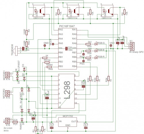
Functional scheme:
Soldering scheme (universal line PCB; e=0.1´´):

Table of components
Code | Type | Parameters | Function |
C1 | capacitor | ceramic 100 nF | IR sensor power filter |
C2 | capacitor | tantalum 10 µF | IR sensor power filter |
C18 | capacitor | ceramic 100 nF SMD 0805 | RC filter of TSOP4838 |
C24 | capacitor | ceramic 100 nF SMD 0805 | MCU power filter |
C25 -C26 | capacitor | ceramic 1 µF | MCP1702 stabilization |
C27 | capacitor | electrolytic 470 µF / 50V | power filter and buffer |
C28 - C29 | capacitor | ceramic 100 nF | driver output filter |
D1- D8 | diode | UF4007 | driver output protection |
D9 | diode | 1N4007 | polarity protection |
D38 - D40 | reflective sensors | QRD1114 | black line detection |
FU1 | polymer fuse | 2.5 A | overcurrent and polarity protection |
IC1 | MCU | PIC16F1847 | microcontroller |
IC2 | stabilizer | MCP1702-5000, 5 V, 250 mA | 5 V power supply |
IC3 | driver | L298N | bidirectional motor driver for two DC motors |
K1 | IR distance sensor | Sharp GP2Y0A41SK0F
| obstacle detection |
K14 -K16 | Connector | ARK500/2 | connectors for motors and power |
PAD1 -PAD5 | pins |
| MCU programming pins |
R1 | resistor | 10 kΩ / 0.6 W | voltage divider for battery control |
R2 | resistor | 17 kΩ / 0.6 W | voltage divider for battery control |
R3 | resistor | 100 Ω / 0.6 W | current setting of QRD1114 diode |
R4 - R6 | resistor | 10 kΩ SMD 0805 | voltage output of QRD1114 transistor |
R42 | resistor | 100 Ω / 0.6 W | RC filter of TSOP4838 |
R49 -R54 | resistor | 1 kΩ / 0.6 W | MCU output to driver protection |
R55 | resistor | 2k2 / 0.6 W | RGB LED current setting |
R56 | resistor | 1k8 / 0.6 W | RGB LED current setting |
R57 | resistor | 1 kΩ / 0.6 W | RGB LED current setting |
RGB | LED | RGB | indication of battery status and sensors positions |
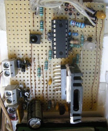
PCB photo:
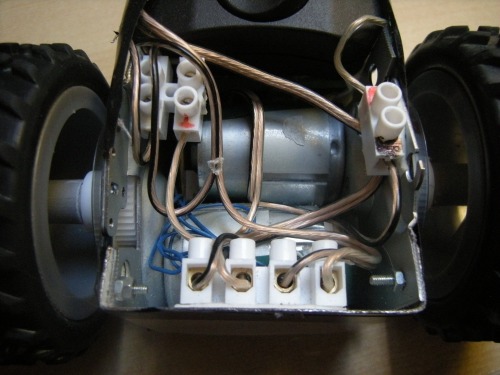
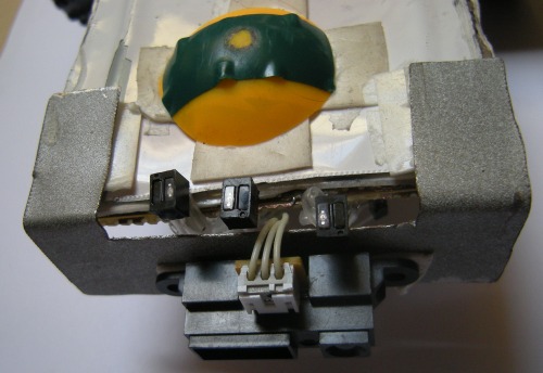
Motor section:
Sensor bottom:
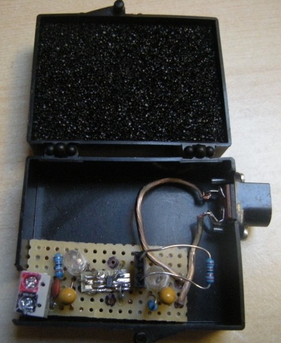
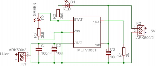
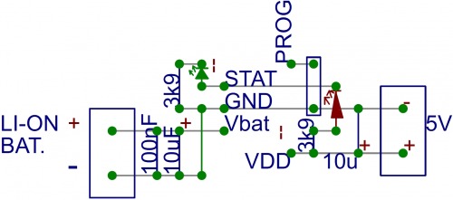
Home-made Li-ion charger was soldered according to datasheet for its chip MCP73831. It is built in a plastic box for Motorola MCU samples. It is able to charge a fully discharged Li-ion accumulator MR18650 (2.2 Ah) in 6 - 7 hours. I plan to make one more PCB of the charger to be able to charge both batteries at the same time.
Charger´s photo:
Charger´s functional scheme:
Charger´s soldering scheme:
What worked ok:
1. Motors from the Canon Pixma i5200 printer are strong enough and quite power efficient for this car.
2. Motor driver L298N has a sufficient capacity for the motors and doesn´t overheat itself.
3. 2 Li-ion batteries have a sufficient capacity for a whole-day racing.
4. Home-made power charger for Li-ion accumulators (but will need to make it double for the two batteries).
What did not work and needs to be changed in the next version:
1. IR distance sensor must be replaced by an ultrasonic sensor to avoid sun-blinding.
2. At least 5 reflective sensors on a separate board needs to be used to cope with the sharp angles on the track.
3. Encoders on motors should be used for better driving around obstacles on the track.
4. LCD display should be used for real-time debugging on the track during training.
5. Bigger MCU (PIC18F46K22) will be used for including all these new functions.
I will welcome your ideas how to improve its design so that I can win and beat my brother Mouse next year!
A line-follower avoiding obstacles and crossing line interruptions, with PIC16F1847, L298N driver, Sharp GP2 IR distance sensor, three QRD1114 reflective sensors and a home-made power charger for Li-ion accumulators