


Balancing Roboduino
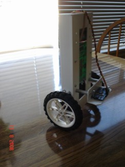
In 2008 I have built a simple balancing robot, mostly a copy from a balancing robot made using a Basic Stamp 2 SX, found on the Parallax Forum, that I have adapted to work on Arduino. The robot uses servos modified for continuous rotation and a Ping))) sensor for balancing. A potentiometer was added to adjust the balancing point, because it depends greatly on the level of the surface. Also I installed a serial LCD to display the distance and the PID values.
I wrote a tutorial on Society Of Robots that got me second place on the tutorial contest and an Axon microcontroller. After I got my Roboduino board, I installed it on the robot and got another video. Because it was suggested to me that I don't have much to show on the LMR site, I decided to bring it all here, as long with my other robots that I have built over time, since this is just a re-write process for me.
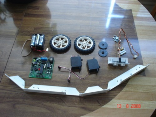
List of materials.
Here is a list of materials needed to build this robot:
- about 2 feet of right angled PVC (or aluminum) bar, 1"x1" wide
- a small box of small nuts and bolts
- 2 standoffs 1 1/2" long
- one Parallax Ping))) ultrasonic sensor
- a Roboduino board
- 2 servos modified for continuous rotation
- 2 large wheels (over 3" diameter)
- a battery box
Building the chassis.
The chassis can be done in different ways. You can get a rectangular board, some double side sticky foam and use it to attach all the parts on the board. Or you can go my way and build a long lasting chassis from a piece of an L shaped right angled PVC (or aluminum) bar.
To minimize the number of nuts and bolts used, I decided to bend the bar in a rectangular shape, like a box frame. I measured the total length and width of the parts for the robot, layed them along the bar, marked both sides of the bar where the bend lines will be and cut one side along the marked line. On each side of the cut I marked a line at 45 degrees, doing the same for the ends of the bar, then I cut them off. Using a pair of pliers I have carefully bended the bar into a rectangular shape. On the outer side, I marked and cut out 2 rectangles to mount the servos, then drilled the holes and mounted them.
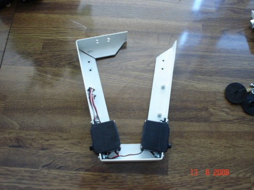
On the interior side (or the bottom of the box frame) I marked the place for the electronics board and drilled the holes for it.
Between the servos and the electronics board, on the bottom of the frame, I marked and drilled 2 more holes to mount the sensor, then I mounted the electronics board.
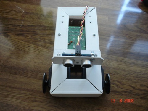
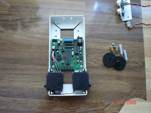
On the top of the frame I have used a rubber band to hold in place a 6 AA battery box. To mount the sensor I needed a piece of the same L shaped PVC bar. I marked on one side the place for the ultrasonic elements and the sensor's LED and mounting holes and drilled them. On the other side I marked and drilled 2 holes matching the ones from the chassis. Using 2 standoffs I mounted the sensor on the chassis, facing away from the end where I mounted the battery box.
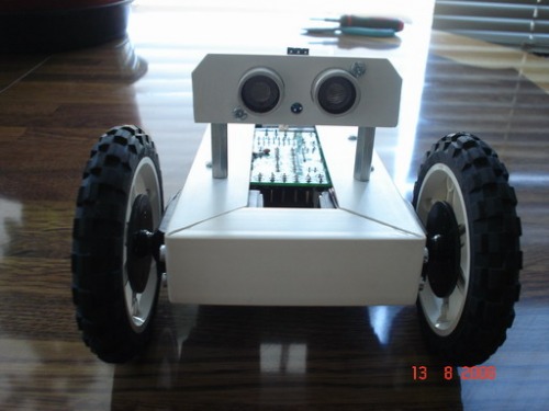
Using a longer metal screw similar with the one that came with the servos, I have mounted 2 large motorcycle wheels from a Lego set, over the round servo horns that came with the servos. You can use any other wheels with a bigger diameter than 3".
Electronic board.
I have used a board that I designed a few years ago, and it is Arduino compatible. At that time I wanted to build a robotic kit similar with Boe-Bot to sell it in Romania, this board was the second version of the PCB for that kit. Here is an image of the board:
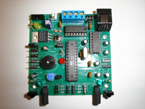
The board has a ATmega8, a SN754410 and a Max232 serial converter. At that time FTDI chips were not popular yet and Arduino was in it's infancy, I knew nothing about it. The board had also built in IR proximity sensors, a buzzer and 3 pin connectors for servos and sensors.
I connected the servos to Digital pins 4 and 5 and the Ping))) sensor to the Digital pin 7. Latter on I added a potentiometer to Analog pin 0.
I also added a serial LCD to be able to display the values so I can tune the PID control easier. It is not mandatory, but works easier than the Debug window. Better add 3 potentiometers to tune each parameter for the PID control with less headache and re-programming.
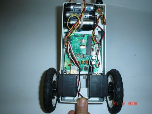
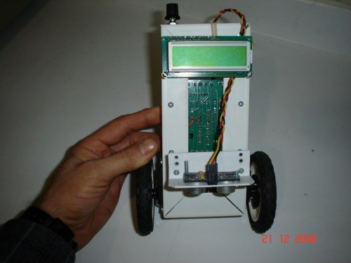
Here are the pictures after replacing the board with the Roboduino:
Program.
First of all, let me explain why the use of Parallax Ping))) ultrasonic sensor. I also have a Maxbotics EZ01 ultrasonic sensor and a Sharp GP2D12 infrared sensor. From all of them, the Ping))) sensor was the most accurate, with stable readings and short response time. I have tryed EZ1 sensor in analog mode and in PWM mode (similar with Ping) but didn't liked the results. The robot could not balance at all. The Sharp sensor was a little better, but it does not offer stable readings in a fixed position, it has spikes from time to time. Probably averaging 5 measurements would get better results. But let's take a look at the code:
As in all Arduino code, we must first set up the pins for the sensors and motors, variables, etc. Then , int Setup function, we set the pin modes and communication.
/* Balancing robot
- uses 2 modified servos for balancing
- uses a potentiometer to adjust the perfect balance point
- uses one Ping))) ultrasonic sensor to read the distance to the surface
- uses a PID control algorithm to adjust the servo pulses so the Ping)))
sensor reading will match the value of the perfect balance point
*/
//Input/outputs
#define PingPin 7 // digital pin 7
#define PotPin 0 // analog pin 0
#define Lservo 4 // digital pin 4
#define Rservo 5 // digital pin 5
#define Led 13 //digital pin 13
//Variables
unsigned int Ptime = 0; // raw value from sensors
int Drive = 0; // PWM value sent to Servos
int Error[5]; // array of 5 Error elements
int P = 0; // proportional term
int I = 0; // integral term
int D = 0; // derivative term
int SetPoint = 307; // perfect balance point value
byte Count = 0; // counter
int Period = 0; // period for generating sounds
int Lwheel = 0; // left wheel variable
int Rwheel = 0; // right wheel variable
int Pot = 0; // potentiometer variable
//tests should be made to determine acurate Min, Mid and Max values for the servos
#define Midl 1460 // center for servos, they should be stoped
#define Midr 1460
//Ping PID constants
#define Kp 2
#define Ki 3
#define Kd 4
//Meaningful names for error array index:
#define Current 0
#define Sum 1
#define Last 2
#define SecondToLast 3
#define Delta 4
void setup() {
pinMode(PingPin, OUTPUT);
digitalWrite(PingPin, LOW);
pinMode(Led, OUTPUT);
digitalWrite(Led, LOW);
pinMode(Lwheel, OUTPUT);
digitalWrite(Lwheel, LOW);
pinMode(Rwheel, OUTPUT);
digitalWrite(Rwheel, LOW);
Serial.begin (19200);
Serial.println("start");
//delay(2000); //wait 2 seconds before start for debug purposes
}
There are 4 functions that are looped at about 20ms: Read_Pot_sensor, Read_Ping_Sensor, PID, Drive_Motors.
void loop(){
Read_Pot_Sensor();
Read_Ping_Sensor();
PID();
Drive_Motors();
delay(7); //wait 7 miliseconds, adjust this value for a 18 to 20 ms loop
}
1. Read_Pot_Sensor.
This function was added to read the pot and set the balancing Setpoint.
int Read_Pot_Sensor() {
Pot = analogRead(PotPin);
//Serial.print ("Pot = "); // debug - remember to comment out
//Serial.println (Pot, DEC); // debug - remember to comment out
return Pot;
}
2. Read_ping_sensor.
The Ping))) sensor has only one signal pin which acts as both trigger and echo. The microcontroller has to output a high signal for 5us (microseconds), then it switches to input mode, waits for the pin to go high, starts a counter and waits for the pin to go low again. At that moment the counter will return the time of sound flight from the sensor to the surface and back to the sensor. If distance is needed, this value has to be divided by 2 and multiplied by 29.034 to get the distance in centimeters or 11.3236 to get the distance in inches. For this application, the time of flight will be stored in the Ptime variable. Here is the code:
int Read_Ping_Sensor() {
//trigger the sensor
pinMode(PingPin, OUTPUT);
digitalWrite(PingPin, LOW);
delayMicroseconds(2);
digitalWrite(PingPin, HIGH);
delayMicroseconds(5);
digitalWrite(PingPin, LOW);
//receive the echo
pinMode(PingPin, INPUT);
digitalWrite(PingPin, HIGH); //turn on pull up resistor
Ptime = pulseIn(PingPin, HIGH);
//print out the value for fine tuning of SetPoint constant
//Serial.print ("Ping time = "); // debug - remember to comment out
//Serial.println (Ptime, DEC); // debug - remember to comment out
return Ptime;
}
3. PID
A simple PID control was used to calculate the values for driving the servos. A Setpoint has to be determined for the perfect balance point by reading the sensor values through the serial port on the computer. To do that, unhook the servos from the board and hold by hand the robot in a vertical balance, read the value and then write it to the Setpoint constant.
For easier variable manipulation, a 5 elements array has been used to store the errors. There is Current, Sum, Last, SecondToLast and Delta, a friendlier name association for the elements of the array. To make the calculations easier, deltaT was considered 1. The result will be stored in the variable Drive. Here are the calculations:
int PID() {
//Error[Current] = SetPoint - Ptime;
Error[Current] = Pot - Ptime;
P = Error[Current] * Kp;
Error[Sum] = Error[Current] + Error[Last] + Error[SecondToLast];
I = Error[Sum] * Ki;
Error[Delta] = Error[Current] - Error[Last];
D = Error[Delta] * Kd;
Drive = P + I + D;
Error[SecondToLast] = Error[Last];
Error[Last] = Error[Current];
Drive = Drive * 4; // we have to multiply the result to get in the 1000-2000 interval
Serial.print ("PID = "); // debug - remember to comment out
Serial.println (Drive, DEC); // debug - remember to comment out
return Drive;
}
3. Drive_motors
The PID result stored in the variable Drive is added or substracted from the Middle point of the servo (the value that makes the servo to stay in place, stopped) and stored in the Lwheel and Rwheel variables . Then the servos are pulsed for an ON time equal with Lwheel or Rwheel variables.
void Drive_Motors() {
Lwheel = Midl + Drive;
digitalWrite(Lservo, HIGH);
delayMicroseconds(Lwheel);
digitalWrite(Lservo, LOW);
//Serial.print ("Left = "); // debug - remember to comment out
//Serial.println (Lwheel, DEC); // debug - remember to comment out
Rwheel = Midr - Drive;
digitalWrite(Rservo, HIGH);
delayMicroseconds(Rwheel);
digitalWrite(Rservo, LOW);
//Serial.print ("Right = "); // debug - remember to comment out
//Serial.println (Rwheel, DEC); // debug - remember to comment out
}
Conclusions.
- This works as proof of concept (balancing), but it lacks fine control.
- The robot balance is heavily influenced by the surface incline level. If you adjust the setpoint for a certain inclination, it will not work properly for a different one.
- The servos do not have a fast enough response (RPM = 60). Use of DC motors with an RPM over 200 is needed.
- To make the robot drive or turn, an Offset variable has to be added or subtracted from the servo pulse variables, this proved to be difficult for this setup.
The next step will be controlling the PWM for DC motors, then replace the Ping))) sensor with an Accelerometer and a Gyro. Of course, some sort of sensor fusion algorithm will be needed, Kalman Filter or something similar. This has already been done by several people, see the Y-bot project.
Simple balancing robot
- Actuators / output devices: 2 servos modified for continuous rotation
- CPU: Roboduino
- Power source: Ni-MH batteries (7.2v total)
- Programming language: Arduino C
- Sensors / input devices: PING))) sonar, potentiometer
- Target environment: indoor flat surfaces