Autonomous Solar Robot Boat
My boys and I are using an Android phone, solar panel, and a bluetooth relay controller to make an autonomous solar robot boat. The phone has display, touch screen, GPS, compass, clock, Internet, and bluetooth. It also has a really great software development environment in App Inventor. The display/touch screen make testing really nice. We can walk around with it showing arrows pointing the way it wants to go and spinning images of propellers on the left and right as it would be controlling the real propellers. So debugging was easier than if we only had the full hardware to test on.
More info at www.islandboys.ai
We can send Morse code with the light or with the horn. The horn is scary loud for inside a house.
The boat is working and motoring around the bay.
The phone/robot uploads GPS and other information to google in real time and google updates a map of the track in real time so anyone can see a map of what the robot is doing on the web.
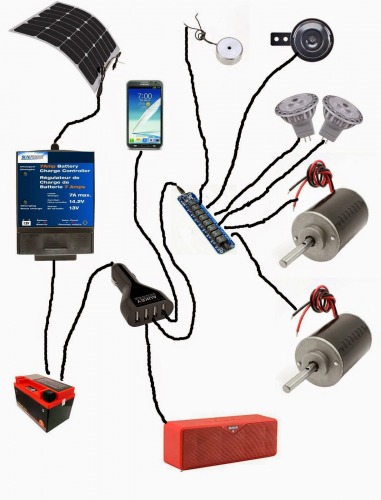
The hardware is very simple really. There are a couple extra things on the drawing below. This drawing shows an electromagnet (which has not come in the mail yet) and a bluetooth speaker which we have not ordered and may not bother with. Also, I went with a smaller relay controller with just 4 relays as the 8 relay can not just get power from a USB. I put a red light on the relay the left motor is on and green light on the same relay as the right motor. So just watching the boat you can tell how much it is using each motor. A really bright white LED is on the 3rd relay. The horn is on the 4th relay. When I get the electromagnet I will put it on the same relay as the horn. I will turn on the electromagnet to push away a regular magnet (or at least that is the current plan) to separate from another boat.
The drawing was simplified a bit by not showing the 12 volt lines going to each of the relays or the ground lines going to the motors, lights, etc. For it to really work you need those wires too. :-)
We have a page with links to most of the parts for this project on Amazon, so it would not be too hard for someone to copy the electronics. We are trying to crowdfund a larger autonomous solar robot boat and the reward for a $50 donation is a copy of our source code. Our App Inventor software is really easy to use or modify. Our software could work with whatever sort of boat design you wanted as long as it had two motors. If you did a monohul you might want to put some space between the motors. So this is a really cool father-son project that is not really that hard.


