


I have been on this site for a while, and have built various robots or electronic circuits and learned a lot during all that time. None of these builds have been published so far, because they remained focused on special technical problems, some of them being work in progress.
Initially, I wanted to use the robot base I had already and modified to have a kind of arm (pan-and-tilt-mechanism) for a camera and TOF sensor to measure distances. Custom made encoders, that keep track of the wheels' position, a custom power supply, several additional levels for mounting various PBCs, etc. Since it's all a rather small form factor, it is a bit fiddly to get right. There are also too many things that need to be really reliable before I could use this base for the autonomous car project.
So I decided to simply use a toy RC car as a basis, a Raspberry Pi, with a power bank, and a remote control that could be modified. Searching the web I even found several projects that did just that, which I used as inspiration.
To get a good overview of how all this works, it is useful to describe the two modes the car can be in.
Operating modes of the car
The car can be either in run mode (autonomous driving) or in training mode (learning to drive).
Run mode (autonomous driving)
The car should drive along a lane whose borders are delimited with paper sheets, on the left and right side. Each camera image from the Raspberry Pi is sent over WiFi and fed into a neural net on the laptop, that has a steering command (either of these: forward, forward left, forwad right) as output. That command gets translated to a set of button presses on the remote control by the Arduino.
This way the RC car drives autonomously along a lane, provided the neural net can extract the relevant features to derive the appropriate drive commands at each frame.
Training mode (learning to drive)
These features are learned in the training mode. To that end, the user can drive the car along a lane, using the cursor keys on the laptop's keyboard. At fixed time intervals the currently pressed keys, together with the current camera frame from the Raspberry Pi cam, are stored in an array. The intervals (and camera image quality) may be affected by network bandwidth or QoS issues, but idealized this procedure gives us a recording of all the necessary information as a sequence of (camera frame, pressed keys)-pairs.
The neural net is then trained with these pairs until the network's parameters are trained well enough that the correlation between camera image and predicted necessary steering command matches well with the examples given.
Many different neural net architecture, or really any kind of machine learning classifiers can be used. There are many possibilities to improve the results by collecting more training data or tuning the architecture, layers, etc.
Once enough training data (=driving examples) are collected and the prediction accuracy of the neural net is satisfactory, it is saved to a file that can be loaded in the autonomous driver program for the car (= run mode).
Overview
In the rest of this post, I'll describe the hardware implementation and modifications that were necessary, but also the software implementation. I will add some relevant code inline. If there is interest, I can post my complete project on github later or link to similar projects, though I am still working on improving the neural network's prediction accuracy.
Documenting this project is a work in progress, so keep checking back from time to time.
To drive the car over the laptop keyboard (training mode) or let the program drive on its own (autonomous mode), the remote control has to be hacked and connected to a microcontroller (any Arduino will do) plugged into the laptop.
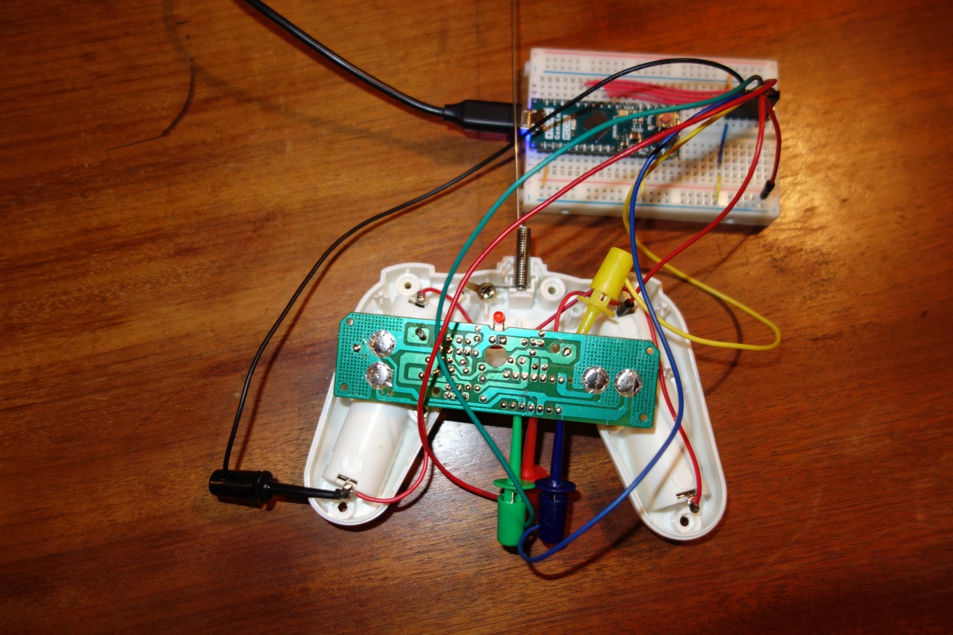
For the model of the car I have, it is rather easy to modify the remote control in a quick and dirty way (no need for soldering, either). You can directly attach probes to pins of the RC's controller chip, from which traces directly lead to the user-accessible buttons. These buttons are purely on/off-switches (no analog signals), which also means you can only drive forward and backward at a fixed speed (ignoring the time necessary for acceleration due to inertia).
The button traces on the PCB are usually at around 3V-3.3V when high. Pulling one of the button traces down to ground will simulate a button press.
This approach however has a couple disadvantages. When unplugging the Arduino, or powering off the laptop, it will automatically pull down some traces far enough to cause the car to drive forward unintentionally. On top of that this is a rather fragile setup, where connections get loose and you get random short circuits just by touching the PCB.
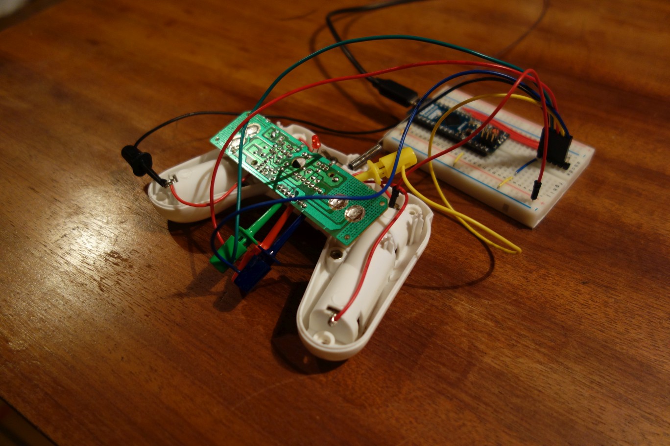
Therefore, I made the effort to really modify the remote control properly, so it works without batteries, directly powered by the microcontroller, and can be closed up again. It took me many days, since I have no 3D printer, and had to invent several tricks to go by with the tools I had. Not the least, to mount the black female header properly into the white casing, so it stays put when you push leads into or pull them out again. (I essentially sculpted a socket out of hot glue, and removed other parts that were in the way.)
Soldering, painting and mounting of female header
Here are some details about the build process, with a comment above each image.
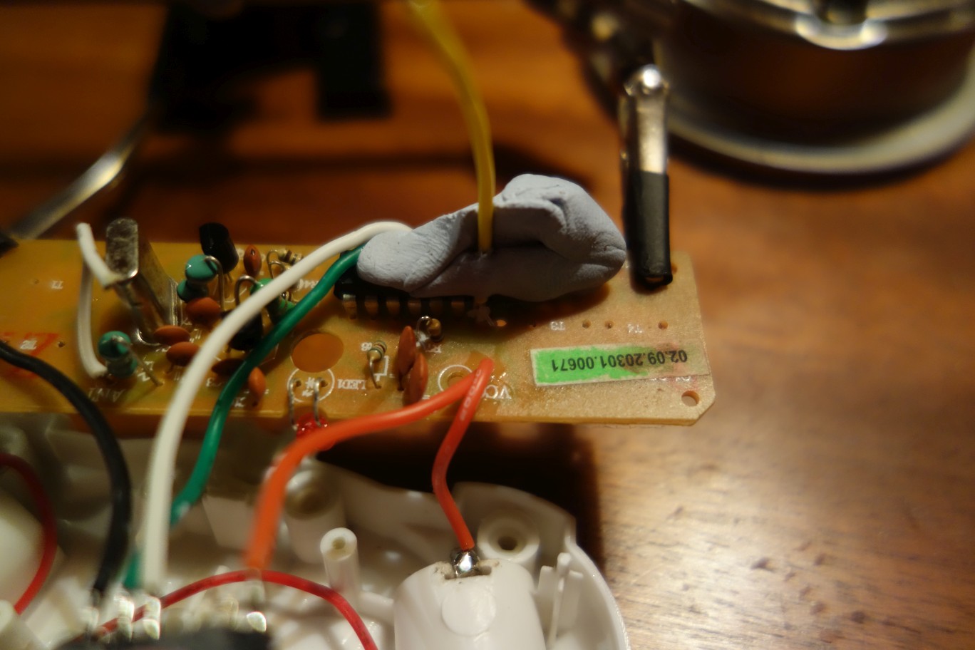
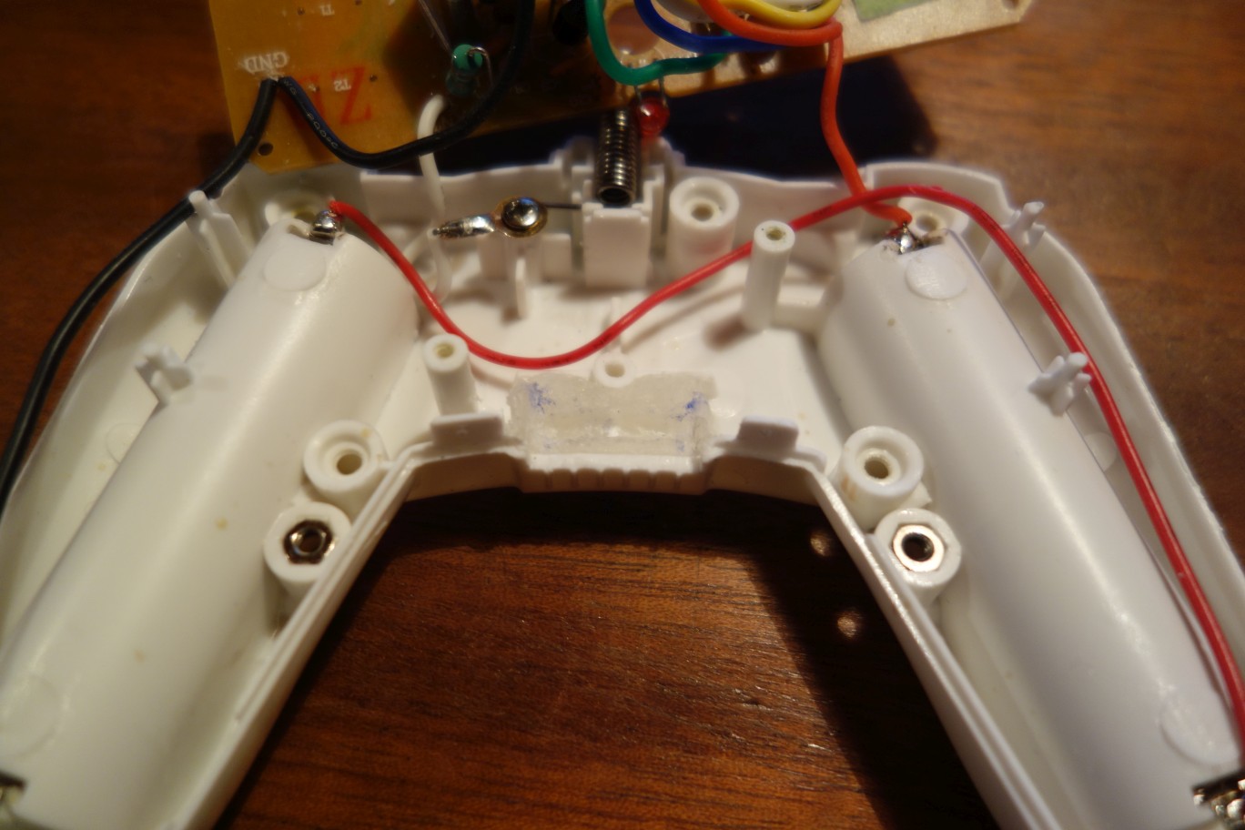
The unmodified board (apart from the VCC cable, which broke off).
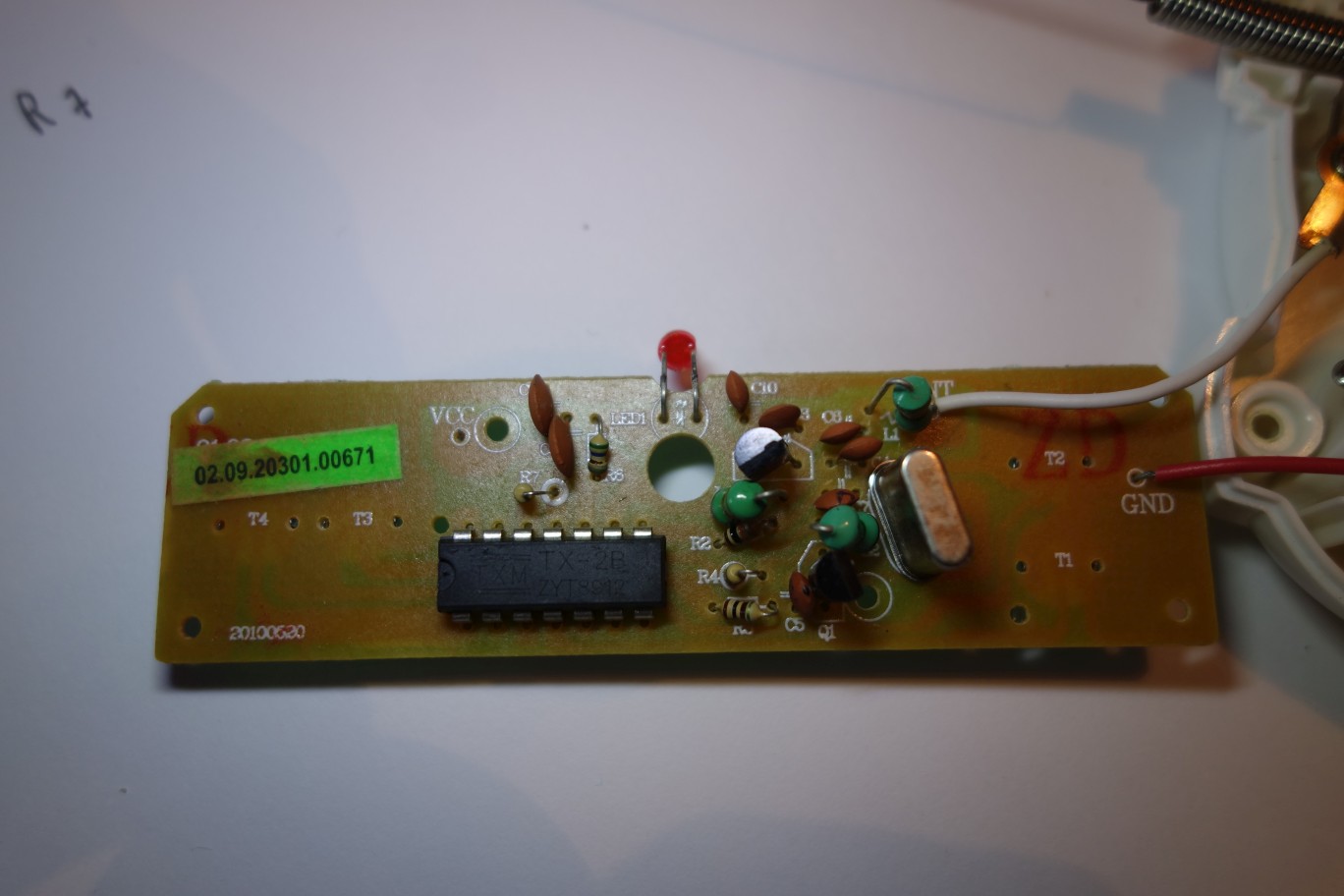
I used bluetack to hold the wires in place when soldering them onto the controller IC.
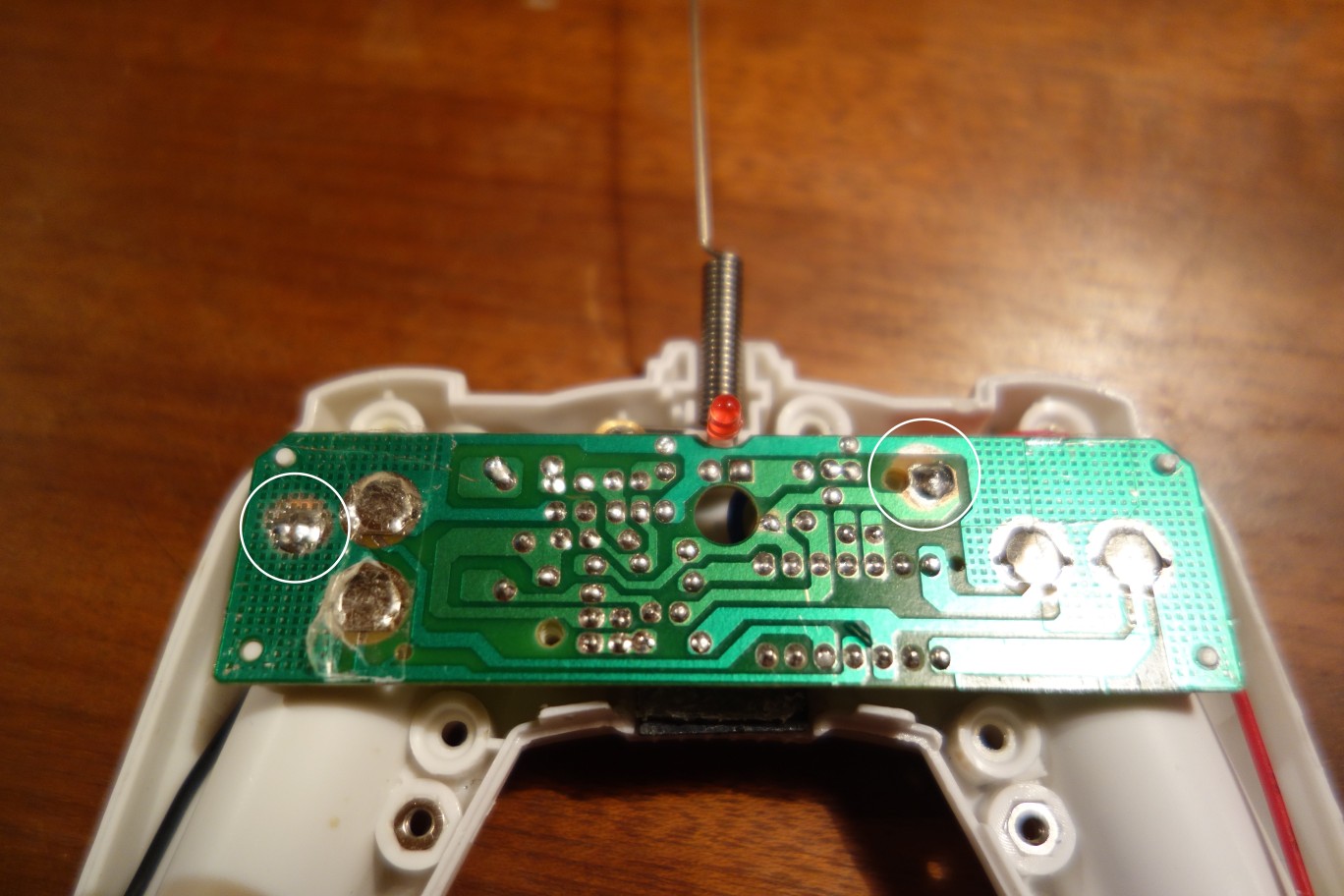
I unsolered the cables for VCC and GND, and drilled bigger holes to fit supplementary cables and make them available from the outside. Using a fiber glass pen I scraped off part of the solder mask, so I had a surface to solder on.
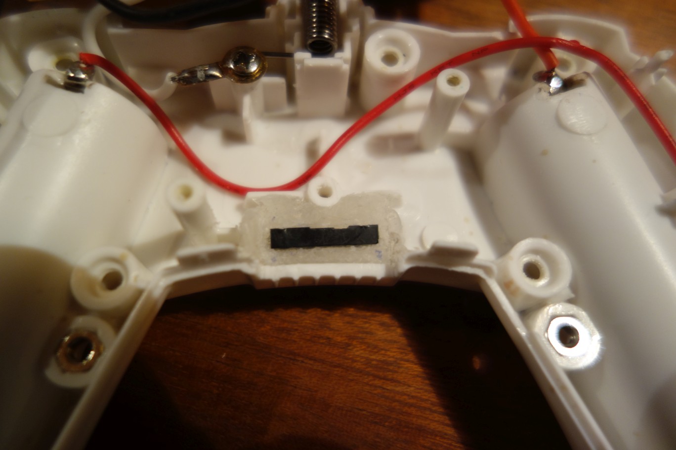
Soldered joints on the IC and female header.
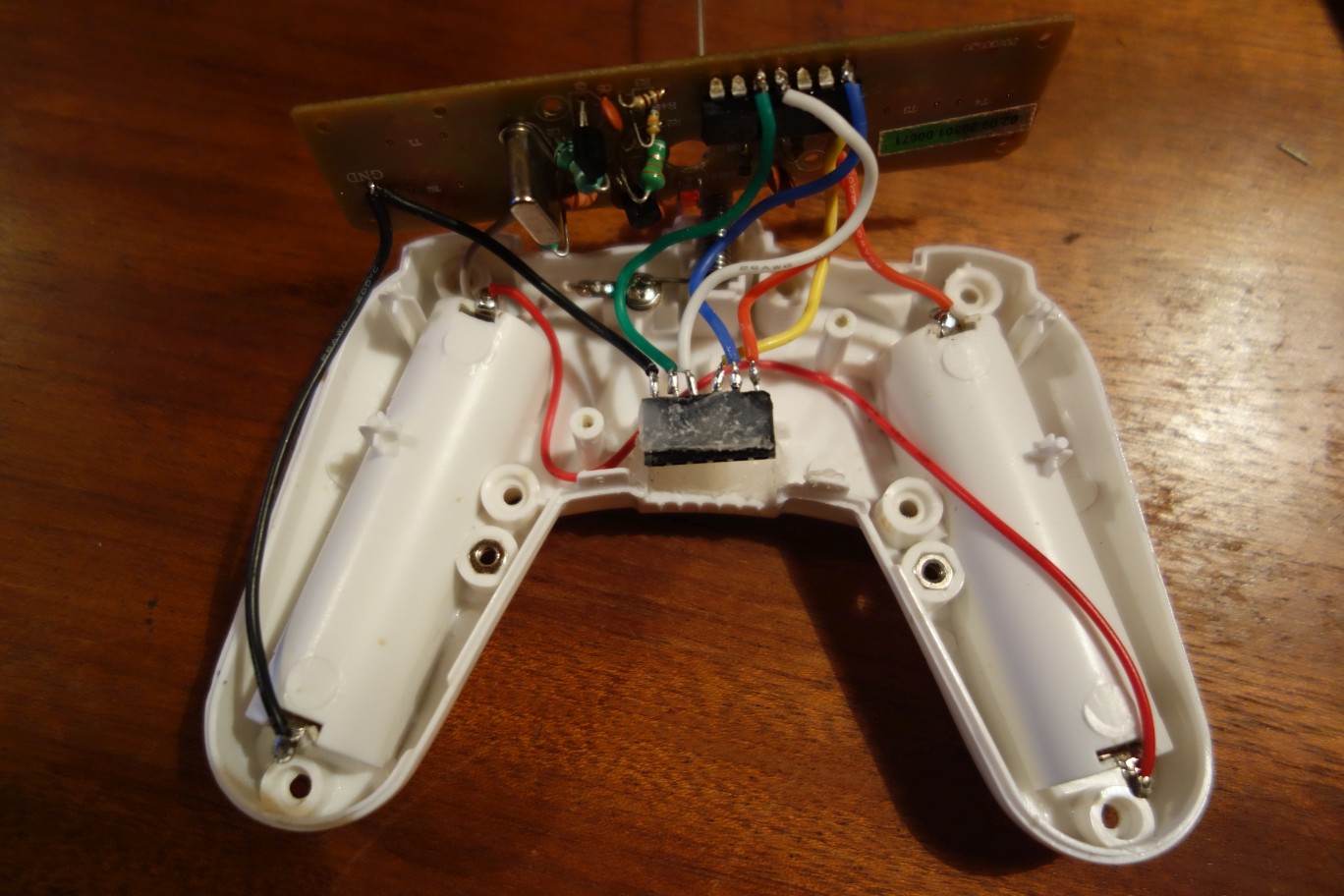
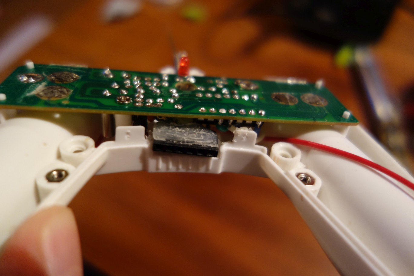
Placement of header when the PCB is mounted again. Hot glue to make the female header higher, so that the top part of the case would hold it down by pressure.
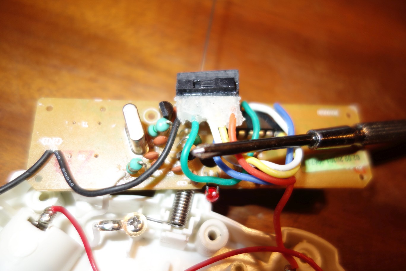
Preparing for painting to isolate pins and avoid short circuits when they get squished close together when everything is mounted again.
Eventhough I put tape and aluminium foil around everything, it still made a mess, and I had to clean each cable individually.
The coating is not perfect, but luckily it covered the solder joints everywhere necessary. I might try nail polish next time.
The pressure from the top part of the case prevents vertical movement of the female header, but horizontal movement when pushing cables or pulling them out is not prevented yet. After various ideas, I cut, saw and used an exacto knife, until I had enough room to put hotglue as a support bed for the female header. I then carved it out to create a hole just the right size to receive a rectangular shape to prevent horizontal movement.
The "male header" end of a jumper wire proved to be the perfect size to act as an anchor for the female header in the hot glue support bed.
I glued it onto the bottom side of the female header, so that pushing the female header down into the carved out hole holds it in place. That way horizontal movement is prevented effectively, together with the pressure provided by the top part of the white RC case.
Now everything can be assembled and disassembled completely, and only pressure/friction and screws hold things in place. So I can open it up and modify it or fix things easily if I need to in future.
Final result
When everything is mounted back together, the remote control looks almost the same, with the exception of a small opening where the female header peeks through.
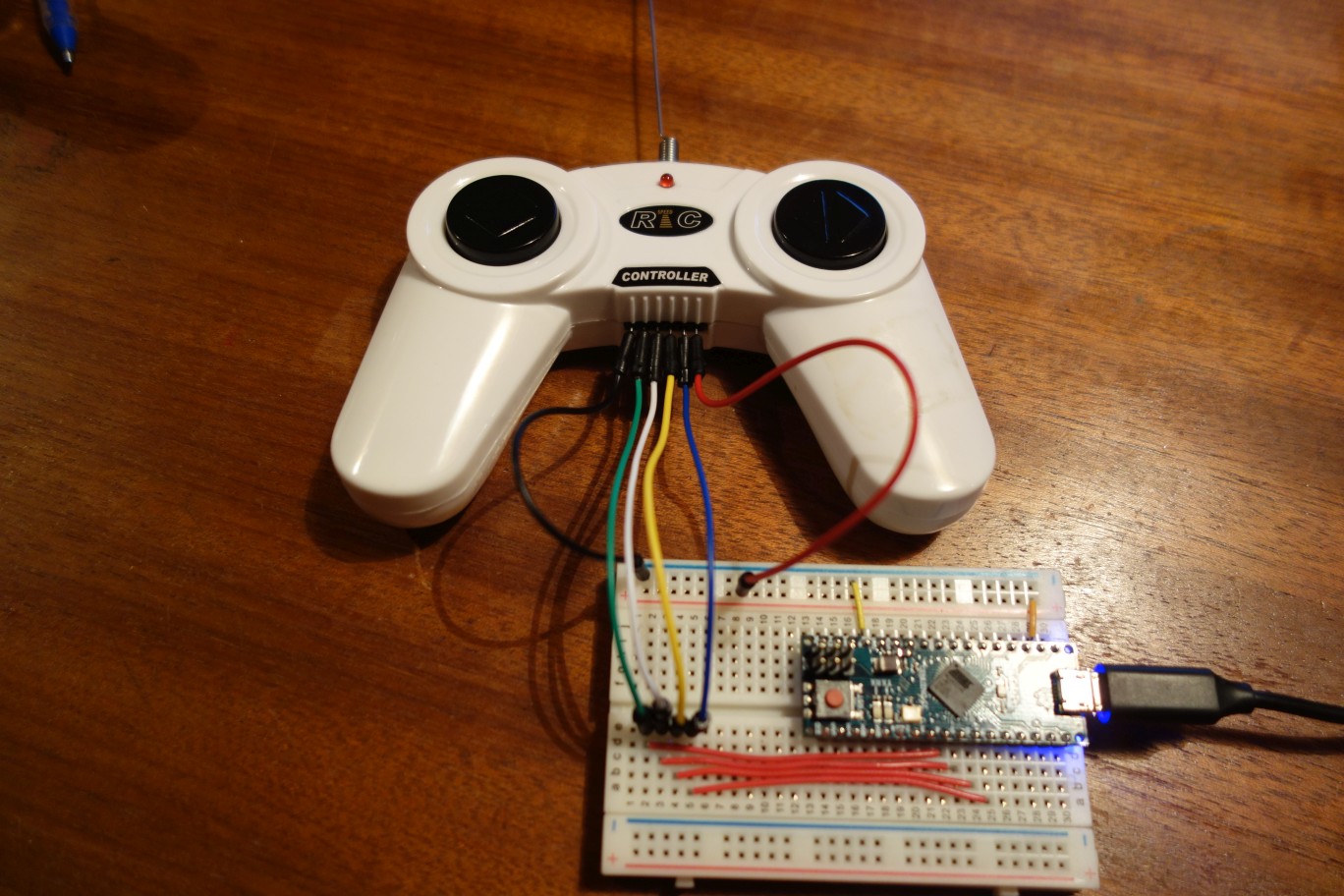
You can remove the cables now, and use the remote control normally, as if it had never been hacked. Though I had quite a few issues initially with cables that broke while working, short circuits, and things that wouldn't fit in the little space, now everything is nice and robust.
Obviously, you can also attach it to a microcontroller with a few cables, to control the car with a PC (which was the initial goal ;).
To drive the car you need a camera and process that data to steer correctly. You could also use photodiodes that point to the ground, to detect the lines that delimit the road by reacting to high contrast differences. But I was interested into using neural nets, which are well suited for processing complex input data, such as obtained from a real world scene through a camera.
Picking the power bank and the RC car model took a while, because I tried to find the car one with the flattest roof, and a power bank which was light enough, yet had enough capacity. Otherwise the spring-loaded wheels are pushed down too much and steering is affected.
Additionally I had plans to react to traffic signs, and mounted the camera properly with screws, but it turned out that you can either point the camera towards the ground, so you see enough of the ground close by, or install it higher up, to see the traffic signs. So for now I decided to focus on the "road". Maybe in future a kind of fisheye lens, or the newer Raspberry Pi Cam v2, which has a larger field of view, could allow to see the road and signs simultaneously.
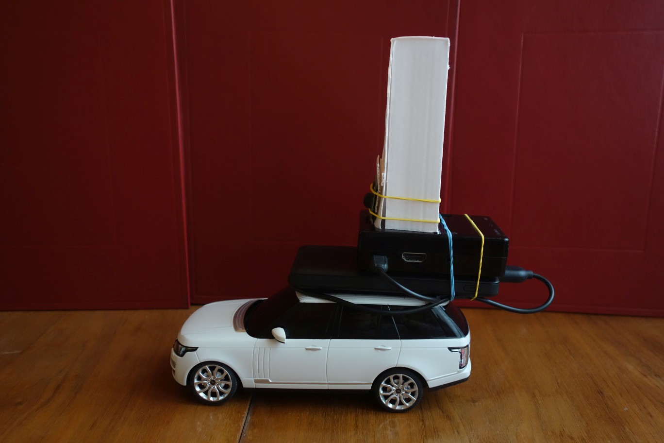
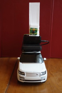
This picture shows the extended car, when it is finished. It has a powerbank directly mounted on the roof, and on top of it a Raspberry Pi in a black casing. The tall white cardboard box is there to mount the camera, which is just held with rubberbands. Initially, I mounted the camera with tiny screws at the top of the box, to capture road signs. But as mentioned earlier, the field of view of the camera is too small to also show the road just in front of the car from this height.
The white cardboard box end was cut and scored to obtain two lids, that could be fixed with double sided tape to the inside of the upper part of the Raspberry Pi casing. I used the slots for the camera and display cable to slide in the lids. Luckily, the base, of the carboard box I had available, fit the gap between the two case slots almost perfectly.
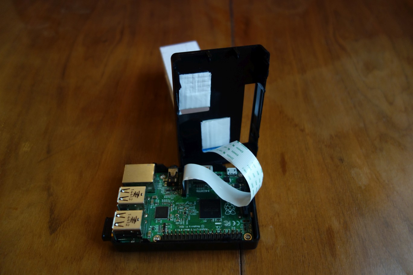
When the camera is mounted with screws at the top, a longer cable is necessary, which is also neatly hidden inside the cardboard box.
The power bank is attached to the roof of the car with velcro, and since the pi's case has some rubber feet, it is enough to use rubber bands to hold it in place. This allows for easier unmounting (which I had to do surprisingly often).
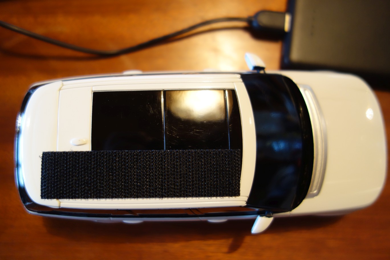
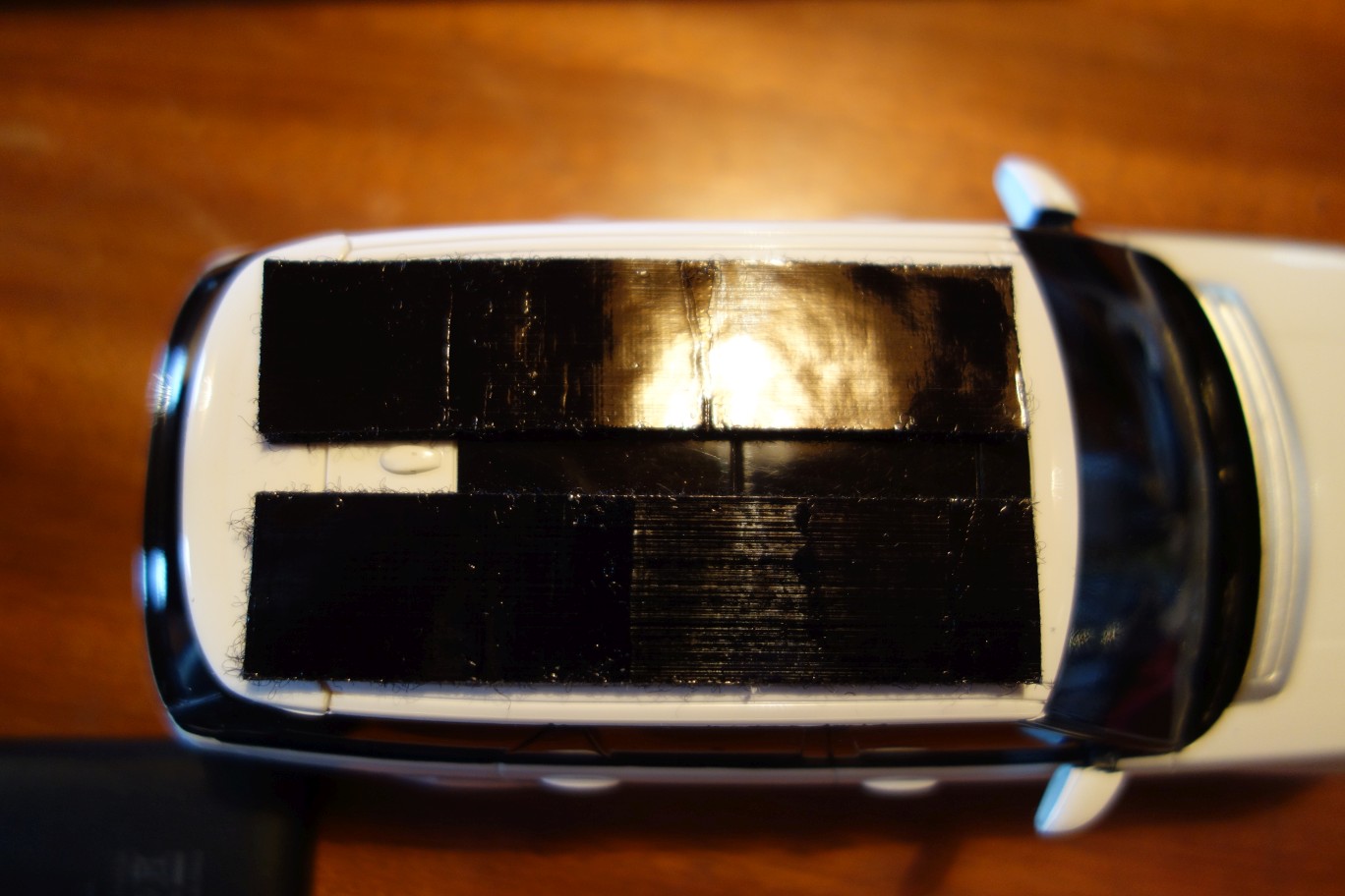
Both velcro counterparts are mounted here, so that I just needed to align the powerbank properly and press it down to glue it on the strips.
Once the WiFi dongle and the powerbank is plugged into the Raspberry Pi, and the cables are held in place with rubberbands, all is set to program the Raspberry Pi for streaming the video signal.
I was looking for a low latency method to stream the Pi cam video to my laptop, since the timestamps of the steering commands and corresponding camera frames should match up as precisely as possible, to take a proper "sensor snapshot" at each point in time.
If that basis is not correct, it may affect training, since the correlation between camera image and required keypresses is the only information the car gets. There are no distance sensors, or wheel encoders, though all of that information could be useful, especially to correct obviously wrong decisions by the neural net. For now I want to keep it reasonably simple, though.
On the Raspberry Pi side the following command should be executed to initiate streaming:
raspivid -n -w 320 -h 240 -fps 60 -b 2000000 -t 0 -o - | gst-launch-1.0 -v fdsrc ! h264parse ! rtph264pay config-interval=10 pt=96 ! udpsink host=<laptop-ip> port=<laptop-port>
It will start the camera and capture a video with a resolution of 320x240 at 60 frames per second with no preview (-n, reduces CPU usage on Pi), streaming it to stdout. GStreamer will pick it up from there (fdsrc) and send it over UDP (for minimum latency) to the ip and port specified under <laptop-ip> and <laptop-port> using Real-Time Streaming Protocol (RTSP). There are other protocols that can be used, such as GStreamer Data Protocol (GDP), but it is less reliable. It will require that the streamer source (Pi) and streamer sink (laptop) be started in the right order, also forcing the laptop to wait for a while to hopefully connect only once the source is ready. RTSP handles all this handshaking properly, and has only a marginally higher latency.
To reduce boring repetitiveness, my code uses plink.exe to run the command remotely once the main Python program runs on my laptop, so there is no need to manually login to the Pi and run the command.
Capturing of the video stream on the laptop is done using OpenCV. Unfortunately GStreamer support has to be enabled manually, and the whole package needs to be recompiled in VS C++, which takes long. Once it is done, replacing the original cv2.pyd (pyd are really DLL files) of your Python installation with the newly created one will enable GStreamer support.
After this the following capturestring will work:
capture_string = udpsrc port=<laptop-port> caps="application/x-rtp, media=(string)video, clock-rate=(int)90000, encoding-name=(string)H264" ! rtph264depay ! video/x-h264,width=320,height=240,framerate=60/1 ! h264parse ! avdec_h264 ! videoconvert ! appsink sync=false'cap = cv2.VideoCapture(capture_string)
appsink is really the essential parameter to make it work with OpenCV's VideoCapture, instead of the standalone gst-launch-1.0.exe.
All of this code was encapsulated into easily useable Python classes, so that streaming is as simple as pulling a frame out of a queue. Since capturing frames runs in a separate thread, it does not delay processing of key strokes that drive the car.
All this recorded data is then stored as NumPy arrays, which are used for training, or inspecting to verify the recording really captured the right frames for each keystroke. (Initially I had problems where the keystrokes and frames would not match up, or the frames where from several seconds earlier.)
Getting all the things right and reducing latency took a while, one of the lessons were that Python's lists are faster at storing the recorded data pairs (keystroke,frame) than using NumPy arrays. So using lists as a temporary buffer, improved latency quite a lot.
I also wrote a little Delphi program to visualize the recorded data, since Python is not really practical for developing interactive GUIs. I could have used C#, but Delphi programs are just snappier.
Currently, I made it drive along a curve. I trained the neural net in one room, but as training is highly specific to the environment (viewed pictures/frames), I have to retrain it for the room that is available to me now.
Later I will add a video and some notes about the programming.
I am in the stage of experimenting with various neuronal network architectures. Probably transfer learning would be the most robust.
Tensorflow is too slow for real time driving, which is why I am using a simple feed forward network currently, as available by OpenCV.
I'll also add links to the references I found on the web, on a future update.
- 18.12.2018 - More details and much more pictures about the modification of the remote control.