


Autonomous Racers!!!
Hello everyone, I’ve posted a lot on LMR, and I build robots for a living, but this is the first time I’ve built a personal robot that I’m able to tell you all about. First off, I got this idea from Fritsl (https://www.robotshop.com/letsmakerobots/node/928 ) and I decided I wanted to build a pair of wall racers for my nephew who has always asked me to build him some robots. If you’ve never heard of a wall racer it is a modified RC car with two sonars, one pointing forward the other pointing to one side. They’re able to race about a track you make out of random stuff.
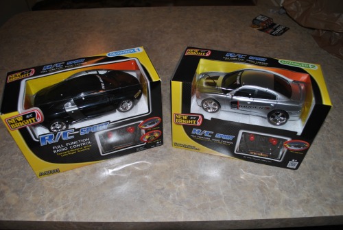
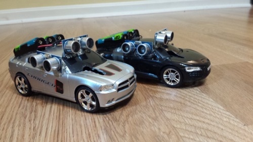
After looking around on the internet for suitable cars, I decided I really needed to see the cars in person before buying them so I went to toys-R-us and bought these two beauties:
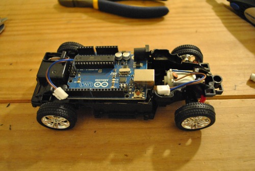
After opening them up, I realized they were exactly the right size for an Arduino UNO
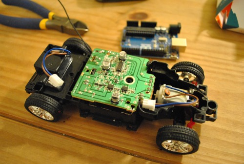
Instead of using relays like Fritsl did, I chose to use a L293D chip. They’re dirt cheap and pretty small. I learned how to use them from this post (https://www.robotshop.com/letsmakerobots/node/2074) (Note: I just used the “simple” circuit and it worked just fine). Here is the circuit I used and a picture that shows my test setup
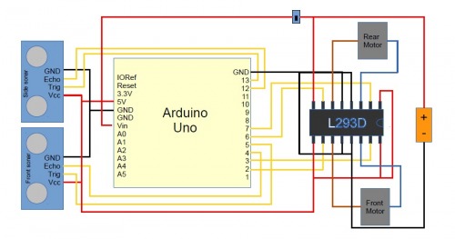
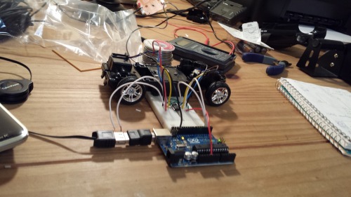
The only components are the 2 motors that came with the cars, the motor driver chip, the batteries, the UNO, two sonars and an on/off switch. To wire everything together I just used wire wrapping which is pretty easy and seems to hold well. I wrote a little python script to test everything out, you’ll see it at work in the video, and here is a link to the code (https://www.robotshop.com/letsmakerobots/node/38172 )
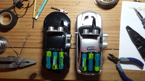
I had to do a bit of dremeling to get the board all the way in and make room for running wires to the sonars and an entry point for the programming cable (that’s the big hole in the windshield/hood). The sonars, UNO, extra battery pack, and power switch are all attached using hot glue (the switch fit nicely where the original one was on the bottom side)
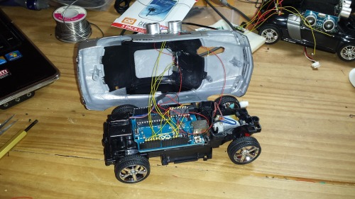
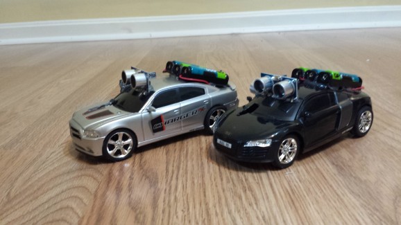
I put a whopping 6 rechargeable batteries on each robot, three underneath in the original spots and three on top! They were only rated at 1.2V so they all gave me just over the recommended 7V for the UNO (I was putting 7V straight to the motors, they seemed to handle it fine). Here are some pics of the finished products:

I tuned them to run great in my office room but once I gave them to my nephew I realized he didn’t really have a good place to run them at his house. I ended up re-tuning them (Christmas morning ha) to work better in their hallway. You’ll notice in my video they were capable of doing some long turns, but I had to take those out for it to work in the hallway, now they only do sliding turns. I also noticed that ground type makes a huge difference in the amount of time you need to pause the motor motion in order to do a slide.
That’s all for now, I’ll also post the cars’ code later, that capability seems to be down right now. Here is a rough outline of the logic:
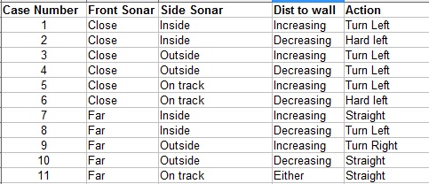
I think it’s pretty self-explanatory. The closer the car is to the wall the harder it turns. The difference between “Turn Left” and “Hard Left” is during a “Turn Left” the wheels steer to the left while the drive wheels keep going. But during a “Hard Left” the drive wheels stop for a small amount of time so its kind of like slamming on the brakes and turning. My actual code was a little more complex than this table and there were some special cases for some situations, but this gives you the general idea.
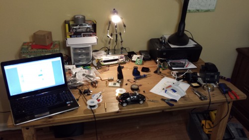
And here's a picture of my workspace during this project just for fun:
Race each other around the room
- Actuators / output devices: DC Motors
- Control method: fully autonomous
- CPU: Ardunio UNO
- Operating system: Ardunio
- Power source: 6 x 1.2V rechargeable batteries
- Programming language: Ardunio (C)
- Sensors / input devices: sonar SRF05
- Target environment: indoor, wide open rooms