


Autonomous Ground Vehicle (Also known as STEVE) 1-14-2014 Update
1-14-2014 Update:
So it’s been a while since I updated, but progress has been made!
So the biggest change was replacing the cheap harbor freight drill motors with two Milwaukee M12 drill motors, which are a huge improvement. These drills have a top rpm of 1500 or 900 depending and 270 in-lbs of torque. Unfortunately, they did not fit. So using a hacksaw I removed the entire front of the robot and laser cut out a new front that the engines did fit it. Unfortunately I did not take photos during this proccess, but it worked out quite well.
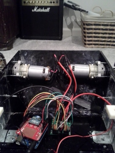
I also ended up replacing the VNH5019 motor drivers for the larger VNH2SP30 which can handle larger currents, up to 14 amps continues and burst of 30+ amps.
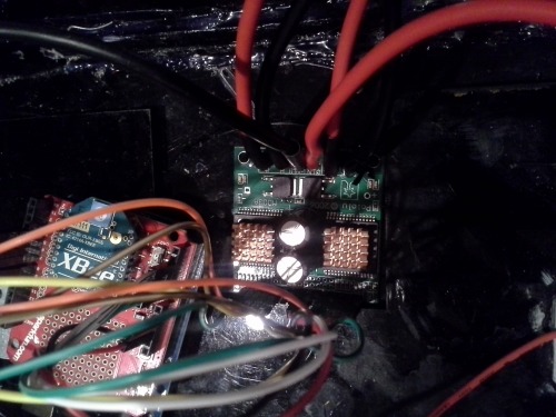
I am still using the Arduino Uno as a temporary control system for testing until I get back to college and can get my hands on a cerebot microcontroller. The Xbee is part of the remote control system, which uses a modified PS2 controller as the user interface.
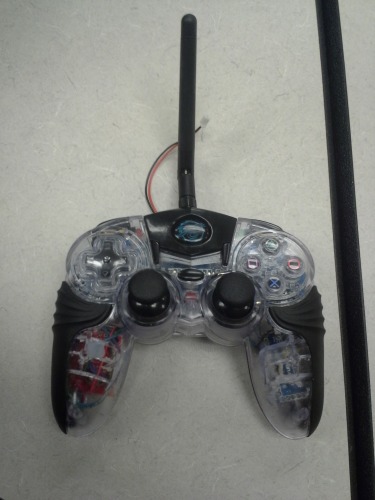
The PS2 controller has been modified with an 3.3 volt Arduino Pro Mini (atmega 328P) running Bill Porter's wonderful PS2X library. The pro mini decodes the signals from the PS2 controller and converts them into serial bytes which are then transmitted by the Xbee and decoded by the arduino on the robot itself. This allowed me to create a 18 channel radio transmitter relatively cheaply.
The next steps are to add an active cooling system and move the electronics to some sort of chassis independant housing. Once I get back to college I would begin contstruction of the "final" version of the AGV, the MK IV.
Thanks for reading! I will be putting up some more videos when I have a chance.
11-3-2013 Update:
With some freetime on my Sunday, I decided to try and finish the second tread section and finish 3D printing out some fiddly bits needed for mounting the top and securing the engines. Unfortunately, the 3D printer was not behaving so I will have to finish printing sometime this upcoming week. Also, since I never did put this on the first update:
Specs:
Drivetrain: 18 volt, 9000 RPM cordless drill motor, VNH5019 Motor Drivers
Power: 12 volt 12 AH sealed lead acid battery
Chassis: 1/4 inch+ cell cast acrylic
Suspension System: 12 10lb 302 Stainless Steel Extension Springs (2 per bogey wheel)
Note: Uses same design for tracks and a slightly modified propulsion method, similar to the Mk II.
Proposed Processor: 32 bit ARM
Proposed Sensors:
9 DOF IMU
GPS
CMU Cam (object recognition and avoidance)
Ultrasonic Range Sensors
 So the top is pretty simple, its just a flat rectangle with holes, but I did have some fun engraving text into it. The holes are over some 3D printed brackets with take an 8-32 nut so I can bolt the top to the chassis. This gives me a nice robust joint while still allowing me access to the inside.
The only annoying thing is the suspension is still a little too soft for my taste so I am ordering a different, strong spring to try.
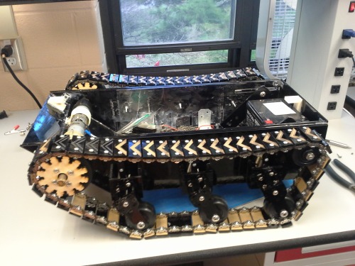
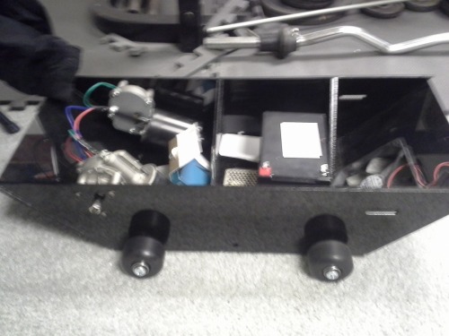
Photo with the top off. It looks a little bit messy because I built the Mark III ontop of the Mark II, and the Mark II suffered from.... structural issues which presented themselves during testing over the summer. Since the chassis was good except for the holes I just glued more panels ontop of the old ones to make it stronger and thicker. Waste not want not right?
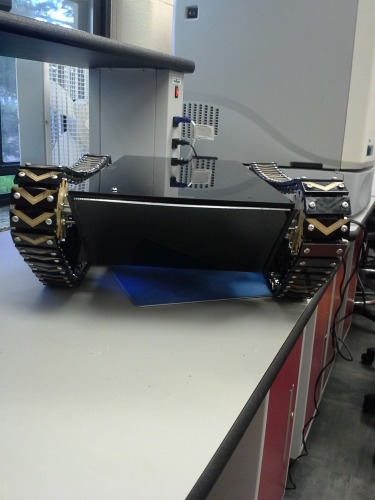
Random front shot:
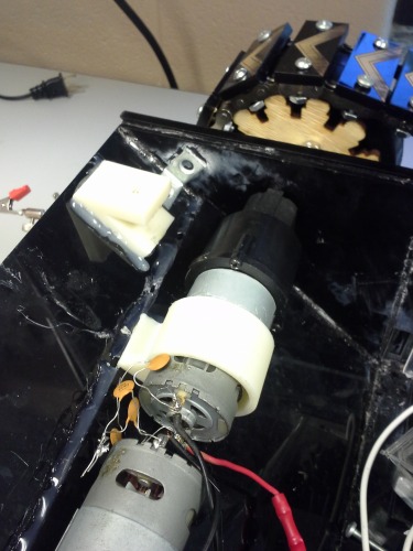
So I designed a mount to help prevent the engine from whiggling, but I ran into an issue, mainly I have to take the engines out to get them on, which is a pain. So I designed a better engine mount which is in two pieces that bolt together. Hopefully this should make my life easier, since taking everything off is a pain. The new mount should be printed sometime tommorrow or tuesday.
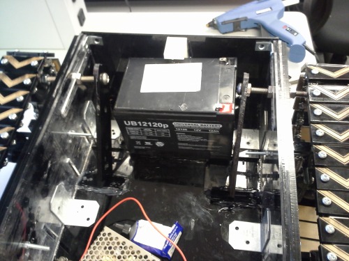
Main Battery and track tensioner. The track tensioner is essentially a ratchet using gaps in the floor support that they fit into. I also glues some old track pieces to help make sure nothing moves. Note, the photo came out weird because I tilted the camera, in reality everything is straight and is not warped the way it looks.
And just for fun an old photo of the Mark I I found lying around on my computer. My favorite thing about working on a multiple interation project is seeing how far you have come and what you have learned along the way. Thanks for reading!
Previous updates:
So this is my first project on LMR, if anything is sub-par please let me know so I can fix it. Now onto the Robot!
Edit: I forgot to put a size, The robot is 22 inches long by 10 inches wide by 9 inches tall with ~5 inches of ground clearance depending.
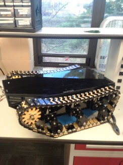
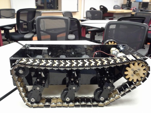
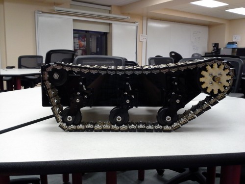
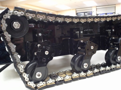
The idea behind STEVE was more of a technical and design challenge to make use of the facilities I have access to after going to college. This robot is the third iteration of the basic concept, which was to implement a tracked all terrain vehicle with a fully articulated passive suspension system to allow it to move at high speed over rough terrain. The suspension system is composed of a plate with semi-circular slots which bolts fit into. This bolts both allow a smooth rotation of the bogey while limiting the motion and providing an anchor in which to attach the springs.
rotation plate:

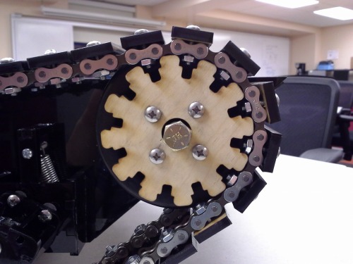
The treads are made from 1/4" laser cut cast acrylic, as is most of the frame and suspension system. The peices are then bolted onto bike chain to form the track itself. The drive train is actually a hybird friction/sprocket drive train where the 1/4" laser cut plywood is designed to interface with the nuts of the bolts holding the acrylic to the bike chain. The sprockets are then bolted to 4" rubber wheels which contact the inner face of the treads. For locomotion the robot uses two cordless drill motors driven by two VNH5019 motor drivers.
Currently I am using an ATMEGA 328P (Arduino Uno) as a control system, but that is just for testing purpose. As soon as the physical mechanisms are finished I will be using a version of a Cerebot board. I've also purchased a CMU Cam (the Pixie) to use for object recognition and detection as well as several HC-SR04s to create a sonar array to help with medium and sort distance obstacle detection.
The only things really left on the mechanical sides are to finish 3D printing the brackets to mount the top to the chassis and secure the engines, cut the rest of the treads then mount them and finally deal with whatever breaks. Plus I've still got designs for robotic arms running around which might be fun to mount on top...
Thanks for reading! If you have any comments, questions, or concerns please feel free to comment! I would love to get other people's opinions on the design before I progress too far to correct any major flaws. :)
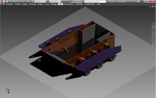
And now pictures:
Overview:
Drive train:
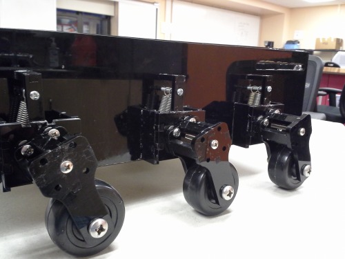
Bogey with and without treads:
Autonomously navigates rough terrain, later option for tele-operation
- Actuators / output devices: 18 volt Cordless drill motors
- Control method: ZigBee (XBee) wireless
- CPU: PIC32 32-bit MIPS processor
- Power source: 12 volt sealed Lead Acid
- Target environment: Outdoors or indoors