All the small things are packed in a small bag, and there is also a PCB board (I forgot to take it in the photo, it is in the shape of a kitten, a little cute?), and then packed in a small paper box. When I received it, the packaging was intact and not damaged, and all the accessories were complete, but it should be noted that many things are very small, so be careful not to lose them...
Let's see what accessories are there: two yellow wheels, 11 resistors, 1 long screw and nut, 4 wires, two capacitors, 1 LM393 chip, 2 photoresistors, several LED lights, 1 switch... ok, let's start!

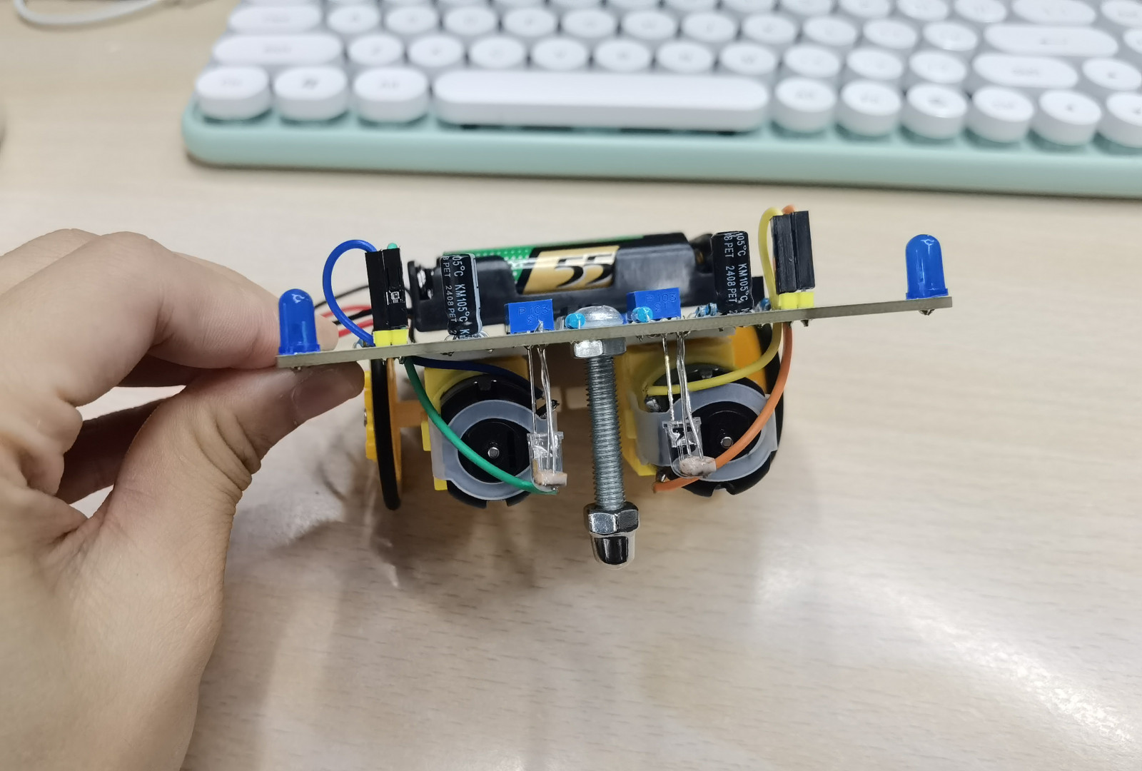
Assembly is straightforward, start with the lowest components (the resistors, usually), and solder them to the PCB as directed, paying attention to the silkscreen for LED & eCap polarity and others as needed. I suppose it took me about an hour, I've been soldering for some years (we won't discuss how MANY years!), and it wasn't difficult at all. The possible problem areas might be the 2 pair of LED/LDR's, which are soldered on the BOTTOM of the PCB, where the solder pads are... so you're kinda soldering them in 'backwards', be sure to leave the leads long on those components so you can get your iron in under them. They need to be long anyways to shine on surface and detect reflected light (or not).
The gear sets, axles, wheels and motors were fiddly to assemble, you may need three hands to keep the axle and its supports aligned while you tighten the screw on the other side of the PCB. You'll get it... but you may need to try a couple of times to get it all lined up, I did. Get one screw going good, suddenly the other axle support rotates away from its position. GRRRR! Sometimes blue-tak or masking tape can be very helpful!
I have a grumble, I feel the battery holder should be installed LAST, as if you're not really careful centering it and keeping it away from other solder holes/pads, you'll have difficulty placing the four wires to power the two motors. The motor power wires must be inserted into small pads which are very close to the side of the battery holder. I'd really recommend leaving the holder until last, as you'll have more room to get your fingers, pliers, tweezers, chopsticks... whatever... in the area to connect the motor wires. Then solder the two leads for the battery holder, wrap the wires around the PCB, double-sided sticky tape the battery pack in place, and voila! Examining my car, I placed the battery holder a bit off-center (only a teensy bit!), crowding the M1/M2 motor wire contacts. just FYI.
Now the really fun bit! Turning it on and tweaking the two potentiometers! This is where I'd like to have a blurb in the instructions describing the potentiometer functionality. Yes, you can figure it out by playing with them, the schematic is very helpful as you can determine that they are bias voltage level controls for the dual op-amp trigger levels. And they interact with each other a little bit, so that can frustrate a less experienced kit builder.
Basically, they set the threshold for the two LDR's (Light Dependent Resistors). Depending on how much light is reflected back by the surface, the resistance of the LDR changes, changing the voltage presented to the inputs to the dual op-amp (LM393). If the voltages differ, the op-amp output either goes to Vcc or Gnd, depending in which voltage is higher (wikipedia has a good article on op-amps, check it out). If the output is low (Gnd), it turns on its appropriate transistor and energizes a motor. If the output is high (Vcc), it turns OFF the transistor (PNP) and the motor is de-energized, stopping it.
You'll have to tinker with the potentiometer settings to get Mr Smart Car to behave, My experience thus far is to start both pots at dead center, and with the power on, tweak them every so very very slightly CCW (counter-clockwise). My car likes to go to the right preferentially, sometimes I can get it to go left... but generally he likes going around the track in a clockwise direction. Your experience will likely vary from mine. You'll swear it has a mind of it's own though.
I put it on a piece of paper provided by the buyer and it ran very smoothly, it was a very happy moment!
I took it to my workplace and showed it to my colleagues, people picked it up and ran it again, we all had a lot of fun!
I like this kit very much and may order a few more to give to my friends and their children, maybe I can inspire their interest in electronics, which is really meaningful!


