


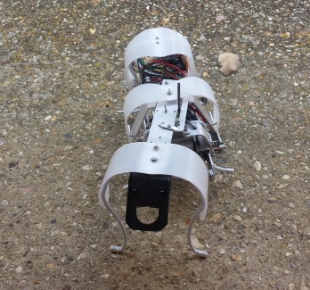
Armora- the armoured caterpillar
28 Sep 2014 Mechanism and video update:
1st video : Description and Mechanism
2nd video: Full working order
3rd video: Testing with battery
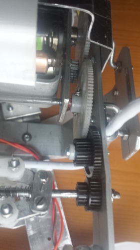
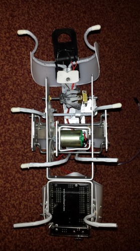
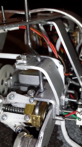
Mechanism: The RPM, from motor, via gear, steps down 12:1(approx) to the main axles' gears. From the main gears, via two little gears(cogs), it steps up 1:5(approx.) to the governer. The main gears are attached directly to the main axles and rotate them. Two axles rotating in tandem create the forward or reverse movement (more explained in the 1st video). The freewheel also rotates simultaneously and controls the steering rod depending on the speed of rotation.
The legs are fastened to the bodies and do not move. Rather, there are two parts of the body. While one part is in contact with the floor via the legs, the other part rises and moves forward and places itself on the floor. Now it is the other part's turn to do the same. The first and third set of legs are attached to the first part of the body. The second and fourth set of legs are attached to the second part. Balance is maintained at all times.
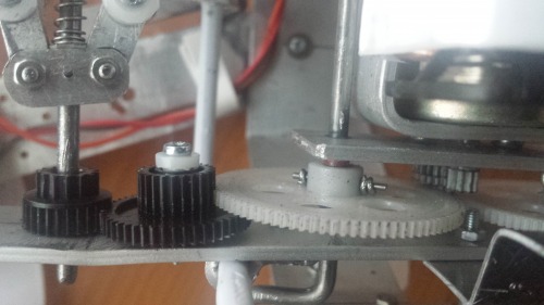
View from below and right side of the bot: Transmission from main gear to Governer
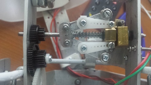
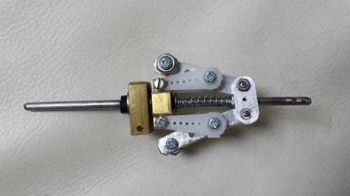
View from below and back to front: Governer
View from belo and front to back:
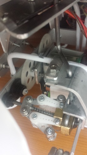
View from top and front left: Governer and steering rod.
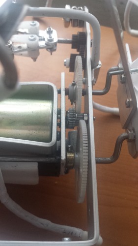
View from top and back-right towards the front: Gears and motor
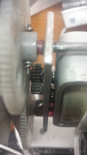
View from bottom front to back: Step down gears from motor.
15 Sep 2014;
This project is now complete for me although i haven't explored reverse movement. Thanks to Yahmez for the challenge.
Materials:
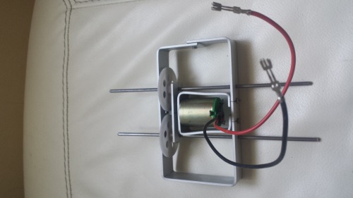
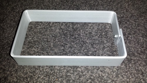
Aluminium flat bar for body frame ---
coat hangar for legs---
plastics for skin-
2mm and 3mm nuts/bolts
2 large rc heli main rotor gears 72 teeth
other various little gears (salvaged)
2 phototransistors
2 microswitches
1 dc motor brushed
jumper wires
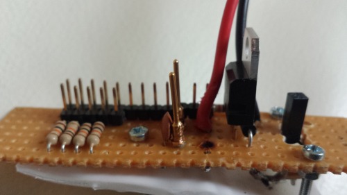
a small pinin/pinout board which incorporates tip120 and limiting resistors (i made myself- 'switching circuit from arduino example').
(a H-bridge if used will allow movement in both directions and left right movement as well.)
Arduino Uno clone from sainsmart(overkill-thats all i had at home)
6 X AAA Nimh rechargeable batteries for power (around 7.8 volts)- provides both motor and clone board.
Mechanism
The large gears are tethered together so the axle move together in same direction at any one time. The 'walking movement' is just another expression of a circular movement.
The centrifugal governer steers the bot depending on the speed at which it is spun.
I used PWM and on/off the motor for finer control.
Code i used is below. I know only little coding.
//Rai. caterpillar_armora//160914
int switch1 =2; // ^ select input for use with switch 1. interrupts available in pins 2 and 3 only
int switch2 =3; // (( | select input for use with switch 2
int photo1 = A0; // v select the input pin for phototransistor 1
int photo2 = A5; // select the input pin for phototransistor 2
int val1 = 0; // variable to store the value coming from phototransistor 1
int val2 = 0; // variable to store the value coming from phototransistor 2
int diff =0; //int to store difference between val1 and val2
int val3 = 0; // variable to store the value coming from switch 1
int val4 = 0; // variable to store the value coming from switch 2
const int motor = 11; //digital pin 11 assigned to motor
int flag1 = 0; //variable to store state of switch1 returned from val3 (position of traction bar)
int flag2 = 0; //variable to store state of switch 2 returned from val4 (position of traction bar)
//ISR 1
void readSwitch1(){
if (digitalRead (switch1) == HIGH)
{flag1=1;
flag2=0;}
}
//ISR2
void readSwitch2(){
if (digitalRead (switch2) == HIGH)
{flag1=0;
flag2=1;}
}
//xxxxxxxxxxxxxxxxxxxxxxxxxxxxxxxxxxxxxxxxxxxxxxxxxxxxxxxxxxxxxxxxxxxxxxxxxxxxxxxxxxxxxsetup below
void setup(){
Serial.begin(9600); //comms to monitor for testing only
pinMode(motor, OUTPUT); // set pin 11 as output.
attachInterrupt(0,readSwitch1,RISING);
attachInterrupt(1,readSwitch2,RISING);
delay(3000);
//initial movement to determine position
analogWrite(motor,150);
delay(500);
analogWrite(motor,0);
delay(2000);
}
//xxxxxxxxxxxxxxxxxxxxxxxxxxxxxxxxxxxxxxxxxxxxxxxxxxxxxxxxxxxxxxxxxxxxxxxxxxxxxxxxxxloop below
void loop(){
val1 = analogRead(photo1); //read phototransistor1
val2 = analogRead(photo2); //read phototransistor2
diff = val1-val2;
Serial.println(diff); //for testing only to find the 'sweet spots'
delay(500);
//left turn
while (diff>30){ //calling the left_turn function
left_turn();
val1 = analogRead(photo1); //
val2 = analogRead(photo2);
diff = val1-val2;
Serial.println("left");
}
//right turn
while (diff<-30){ //calling the right_turn movement
right_turn();
val1 = analogRead(photo1);
val2 = analogRead(photo2);
diff = val1-val2;
Serial.println("right"); //for debugging only
}
//straight ahead
while (-30<=diff<=30){ //straight_ahead movement
straight_ahead();
Serial.println("straight"); //for debugging purposes only
delay(50);
if (flag1!=0 && flag2 !=0){
break;}
val1 = analogRead(photo1);
val2 = analogRead(photo2);
diff = val1-val2;
if (diff>30 || diff<-30){ //for exiting the while loop
break;}
}}
//xxxxxxxxxxxxxxxxxxxxxxxxxxxxxxxxxxxxxxxxxxxxxxxxxxxxxxxxxxxxxxxxxxxxxxxxxxxxfunctions are below
void straight_ahead(){
diff=map(diff,-30,30,150,255);
diff=constrain(diff,150,255);
analogWrite(motor,diff);
delay(20);
analogWrite(motor,0);
delay(50);
}
void left_turn(){ //left_turn function
//had to individually assign PWM on and off times for each movement
//as the two parts of the bots are unequally weighted.
while(flag2==1){
analogWrite(motor,200);
if(flag2!=1){
break;
}}
while(flag1==1){
analogWrite(motor,255);
delay(5);
analogWrite(motor,0);
delay(60);
if(flag1!=1){
break;
}}
}
void right_turn(){ //right_turn function.
while(flag1==1){
analogWrite(motor,150);
delay(20);
Serial.println("right turn"); // for testing only
if (flag1!=1){
break;
}}
while(flag2==1){
analogWrite(motor,150);
delay(5);
analogWrite(motor,0);
delay(200);
if (flag2!=1){
break;
}}
}
Hello LMRians and everyone, meet Armora, a young caterpillar from a mythical land. It aspires to become an armoured caterpillar someday to join its bigger brothers in their protracted war against a formidable enemy, the Aphids, a large ferocious tribe of tiny creatures who are well organised. The caterpillars have been driven away or subdued in their land, and legend has it that Armoura grew up indeed to become an armoured caterpillar and drove the Aphids out of the land but not before its own many adventures or misadventures.
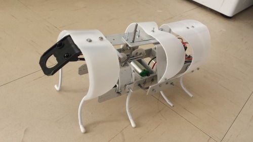
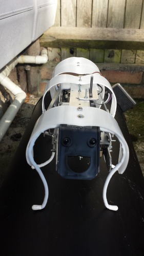
Armora is a single motor bot. Its design allows it to go forward, reverse and turn left or right in both. I am working to make it follow light. I have finished the mechanical build and am stringing the electronics. If completed in time, i will nominate it for smc.
More details to follow.
capable of moving forward, reverse left and right using single motor