


Arduino Sumo Robot Prototype
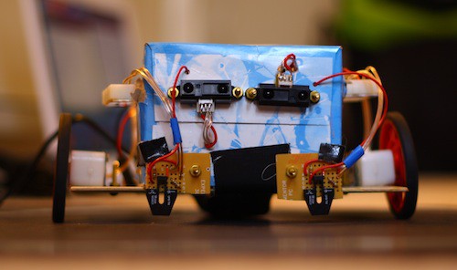
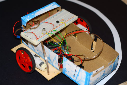
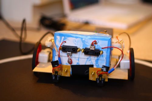
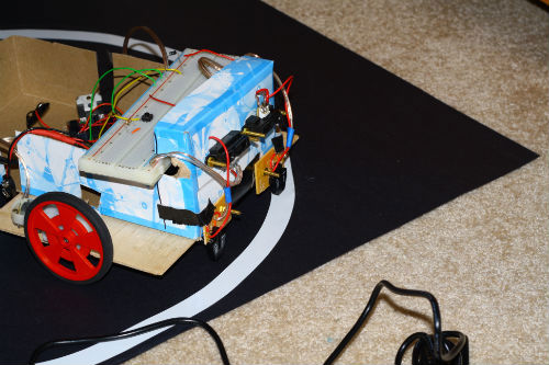
This is the fully functional test chassis for my Arduino based sumo robot. It will be competing in March, 2011. For the prototype I am using a piece of plywood to mount the motors, and a Kleenex box to house the electronics and to use as a mount for the IR distance sensors and the line sensors. This is mostly meant as a chassis to test code, and it does not reflect the weight or size of the final sumo robot.
One of the main reasons I wanted to build this robot was to have a platform with which to test different code. With a sumo robot style base, you can program obstacle avoiders, line followers, or combine the two to make a sumo robot for competition purposes. I I had to go from scratch with the code because there are not very many Arduino sumo robots documented on the Internet. I only found one on LMR!
Hardware:
Motors: Solarbotics GM9 motors with Solarbotics mounts and GMPW wheels.
Line Sensors: OPB704 reflectance sensors with custom power and interface board.
Distance Sensors: Sharp GP2D12 4-80cm rangefinders.
Brain: Arduino Duemilanove with code I wrote from scratch.
Motor Drivers: One Solarbotics L298 Compact Motor Driver.
The robot is currently powered by two 9 Volt batteries. One powers the Arduino, and the other powers the motor driver board and the sensors.
Tip:
To get an Arduino to work with an L298 Compact Motor Driver kit, you need to connect the GND pin of the Arduino to the negative terminal on the motor driver. This way, the driver and the Arduino share a common ground, enabling the arduino to turn the inputs of the driver on and off. This is needed to control the motors with Arduino's 5v digital output pins when the motors are using a different voltage source. A 9V battery, for example.
Software:
The code for this robot is actually very simple. The start function waits for the start button to be pressed after the setup function sets up the I/O pins. The main loop which runs over and over again contains If/Else If statements.
Start (runs once at the start)
- Wait for the start button to be pressed.
- When it goes high, blink an LED for five seconds.
- Go to main loop.
Loop (runs over and over)
- Read the line sensors. If either one or both of them is over a threshold (white is seen), back up and turn.
- If the line sensor values are below the threshold, (black line is seen) continue without moving.
- Check if the analogue value from one distance sensor plus a threshold value is still less than the analogue value from the other distance sensor.
- If this is true, turn towards the second sensor in attempt to get both square with the opponent.
- If both sensors are within a certain range, go forward because there's probably an opponent there.
- If both sensors are below a certain range, turn left around the ring to try to detect the opponent.
- Repeat.
Benefits of PWM:
In this project I am using PWM to control the motors. I think everybody should use PWM (pulse width modulation) to control motors. This eliminates the need for motors to slow down in order to stop. You can stop or change direction on a motor virtually instantly. This is the same technique servos use for their precision, but they have the advantage of position feedback as well.
PWM pulses the enable pin on my motor driver on and off very fast. In the Arduino environment, you can set how fast it pulses to control speed on the fly as well. For example, 255 if full speed so 127 is half speed and 0 is off. In Arduino, I use analogwrite(m1PWM, 255); to control the speed of the motor. When switching from forward to reverse, PWM allows for more precision too. It provides smooth, incredibly quick transitions between directions. Because of that, I recommend PWM on any robot where motor precision and fast direction changes are crucial.
Future:
As I said, I will be entering this robot in a competition in March. By that time, it will be past the prototype stage of course. On the final robot, I will be using two BaneBots motors for the drive system instead of the relatively slow Solarbotics GM9's. The chassis will be made out of lightweight sintra with a sheet metal scoop to hit opponents and protect the rangefinders. The Solarbotics motors are way easier to test code with because they're slow and you can see what is happening. I will most likely be using an Ardweeny from Solarbotics as well as some lightweight rechargeable batteries to save weight.
Conclusion:
I hope you enjoy this article and possibly learn something from it. If you want to see the latest revision of the code or would like more details about something to do with this project, just ask in the comments. I'd be glad to help!
Code Download:
I'm not supporting this project any more. I ran out of time for development before the competition, so I had to scrap sumo and build a line follower instead. You can get the latest revision of the code at the start of this page in the attachments section. Keep in mind the code is built for my robot, so it will require considerable modification to work on your robot. It is mostly intended to show LMR users how I'd program a sumo bot. I may pick up this project again in the future, but I think I will concentrate on line following instead of sumo.
Push other robots out of the ring.
- Actuators / output devices: 2 solarbotics GM9 gearmotors (143:1)
- Control method: autonomous, Arduino
- CPU: Arduino Duemilanove (328)
- Operating system: Arduino IDE
- Power source: 2 9 volt batteries (many options)
- Programming language: Arduino C
- Sensors / input devices: Sharp GP2D120 IR sensor, OPB704 reflectance sensors
- Target environment: indoor, ring, competition