


arduino smartphone app control car using l298
hello guys..
this is our project thats called arduino based smartphone app
control car using l298 motor driver via bluetooth.
sooo lets start....
Step 1: Components
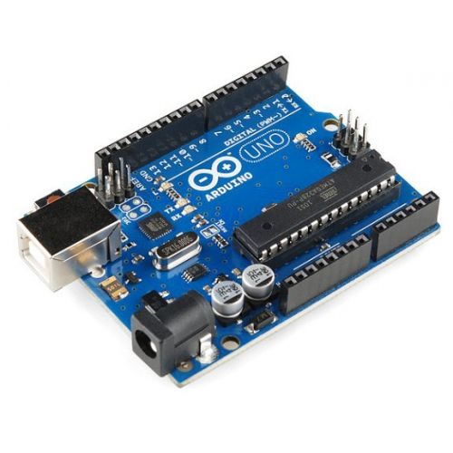
1:-arduino uno
2:-bluetooth hc-05
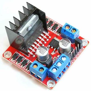
3:-l298 motor driver
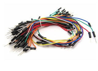
4:-jumper wires
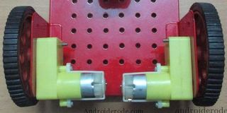
5:-two dc motors
6:-two wheels with caster wheel
7:-one chassis
8:-9v battery with jack
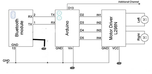
Step 2: Circuit Diagram
here
bluetooth module:-
rx of bluetooth connect to tx of arduino
and tx of bluetooth connect to rx of arduino.
vcc-------+5v
gnd--------gnd
sooo...
2pin of arduino connect to --l298 motor driver in1(left motor)
3pin of arduino connect to ----l298 motor driver in2(left motor)
4pin of arduino connect to------l298 motor driver in3(right motor)
5pin of arduino connect to-----l298 motor driver in4(right motor)
and vcc connect to +5v
and gnd connect to gnd..
Step 3: Uploading the Code
at 1st go to below and download the app to the link
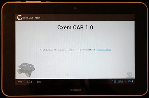
// CxemCAR 1.0 (06.01.2013) from google store
// Project Page: http://solderer.tv/arduino-rc-car/
and below copy this code and paste to arduino and compile the upload to arduino board...
or one matter dont forget thats ....when upload code to arduino board this time must remove tx rx jumper wires from connection...must remember guys...
#include "EEPROM.h" #define D1 2 // direction of motor rotation 1 #define M1 3 // PWM left motor #define D2 4 // direction of motor rotation 2 #define M2 5 // PWM right motor #define HORN 13 // additional channel 1 //#define autoOFF 2500 // milliseconds after which the robot stops when the connection #define cmdL 'L' // UART-command for left motor #define cmdR 'R' // UART-command for right motor #define cmdH 'H' // UART-command for additional channel (for example Horn) #define cmdF 'F' // UART-command for EEPROM operation #define cmdr 'r' // UART-command for EEPROM operation (read) #define cmdw 'w' // UART-command for EEPROM operation (write) char incomingByte; // incoming data char L_Data[4]; // array data for left motor byte L_index = 0; // index of array L char R_Data[4]; // array data for right motor byte R_index = 0; // index of array R char H_Data[1]; // array data for additional channel byte H_index = 0; // index of array H char F_Data[8]; // array data for EEPROM byte F_index = 0; // index of array F char command; // command unsigned long currentTime, lastTimeCommand, autoOFF; void setup() { Serial.begin(9600); // initialization UART pinMode(HORN, OUTPUT); // additional channel pinMode(D1, OUTPUT); // output for motor rotation pinMode(D2, OUTPUT); // output for motor rotation /*EEPROM.write(0,255); EEPROM.write(1,255); EEPROM.write(2,255); EEPROM.write(3,255);*/ timer_init(); // initialization software timer } void timer_init() { uint8_t sw_autoOFF = EEPROM.read(0); // read EEPROM "is activated or not stopping the car when losing connection" if(sw_autoOFF == '1'){ // if activated char var_Data[3]; var_Data[0] = EEPROM.read(1); var_Data[1] = EEPROM.read(2); var_Data[2] = EEPROM.read(3); autoOFF = atoi(var_Data)*100; // variable autoOFF ms } else if(sw_autoOFF == '0'){ autoOFF = 999999; } else if(sw_autoOFF == 255){ autoOFF = 2500; // if the EEPROM is blank, dafault value is 2.5 sec } currentTime = millis(); // read the time elapsed since application start } void loop() { if (Serial.available() > 0) { // if received UART data incomingByte = Serial.read(); // raed byte if(incomingByte == cmdL) { // if received data for left motor L command = cmdL; // current command memset(L_Data,0,sizeof(L_Data)); // clear array L_index = 0; // resetting array index } else if(incomingByte == cmdR) { // if received data for left motor R command = cmdR; memset(R_Data,0,sizeof(R_Data)); R_index = 0; } else if(incomingByte == cmdH) { // if received data for additional channel command = cmdH; memset(H_Data,0,sizeof(H_Data)); H_index = 0; } else if(incomingByte == cmdF) { // if received data for EEPROM op command = cmdF; memset(F_Data,0,sizeof(F_Data)); F_index = 0; } else if(incomingByte == '\r') command = 'e'; // end of line else if(incomingByte == '\t') command = 't'; // end of line for EEPROM op if(command == cmdL && incomingByte != cmdL){ L_Data[L_index] = incomingByte; // store each byte in the array L_index++; // increment array index } else if(command == cmdR && incomingByte != cmdR){ R_Data[R_index] = incomingByte; R_index++; } else if(command == cmdH && incomingByte != cmdH){ H_Data[H_index] = incomingByte; H_index++; } else if(command == cmdF && incomingByte != cmdF){ F_Data[F_index] = incomingByte; F_index++; } else if(command == 'e'){ // if we take the line end Control4WD(atoi(L_Data),atoi(R_Data),atoi(H_Data)); delay(10); } else if(command == 't'){ // if we take the EEPROM line end Flash_Op(F_Data[0],F_Data[1],F_Data[2],F_Data[3],F_Data[4]); } lastTimeCommand = millis(); // read the time elapsed since application start } if(millis() >= (lastTimeCommand + autoOFF)){ // compare the current timer with variable lastTimeCommand + autoOFF Control4WD(0,0,0); // stop the car } } void Control4WD(int mLeft, int mRight, uint8_t Horn){ bool directionL, directionR; // direction of motor rotation L298N byte valueL, valueR; // PWM M1, M2 (0-255) if(mLeft > 0){ valueL = mLeft; directionL = 0; } else if(mLeft < 0){ valueL = 255 - abs(mLeft); directionL = 1; } else { directionL = 0; valueL = 0; } if(mRight > 0){ valueR = mRight; directionR = 0; } else if(mRight < 0){ valueR = 255 - abs(mRight); directionR = 1; } else { directionR = 0; valueR = 0; } analogWrite(M1, valueL); // set speed for left motor analogWrite(M2, valueR); // set speed for right motor digitalWrite(D1, directionL); // set direction of left motor rotation digitalWrite(D2, directionR); // set direction of right motor rotation digitalWrite(HORN, Horn); // additional channel } void Flash_Op(char FCMD, uint8_t z1, uint8_t z2, uint8_t z3, uint8_t z4){ if(FCMD == cmdr){ // if EEPROM data read command Serial.print("FData:"); // send EEPROM data Serial.write(EEPROM.read(0)); // read value from the memory with 0 address and print it to UART Serial.write(EEPROM.read(1)); Serial.write(EEPROM.read(2)); Serial.write(EEPROM.read(3)); Serial.print("\r\n"); // mark the end of the transmission of data EEPROM } else if(FCMD == cmdw){ // if EEPROM data write command EEPROM.write(0,z1); // z1 record to a memory with 0 address EEPROM.write(1,z2); EEPROM.write(2,z3); EEPROM.write(3,z4); timer_init(); // reinitialize the timer Serial.print("FWOK\r\n"); // send a message that the data is successfully written to EEPROM } }
Step 4: Android Application
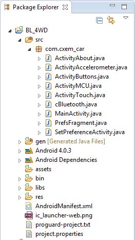
The application for Android was written in Eclipse IDE. All sources of the project and the project for Eclipse, you can download below. Android version on your device must be > 3.0.
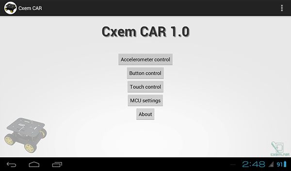
The application contains several activity. Main activity is a home screen with buttons running different operating modes and settings...
There are 3 control modes Bluetooth-car: from accelerometer, screen buttons and touch-control.
Step 5: Android Application Settings
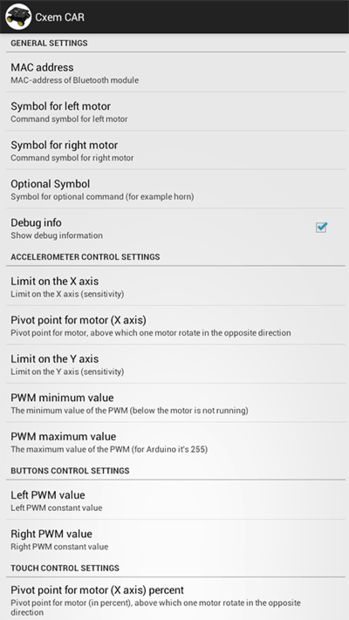
Screenshot of settings CxemCar Android application version 1.0:
Step 6: Mac Address
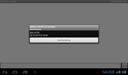
To establish a connection with the RC Car’s Bluetooth module, you must set MAC-address in the application settings. But first, you must configure the pair the devices on Android-device: open Settings -> Bluetooth and click “Search for devices”. When the phone finds our Bluetooth-module, click them and enter password for pairing (usually “1234”)
To know Bluetooth module MAC-address possible from any application, such as Bluetooth Terminal. To do this, click “Connect a device – Secure” and in the resulting window, click the button “Scan for devices”. Software will be scans the Bluetooth devices and displays them MAC-address.
Obtained MAC-address needs to be set in the Android-application CxemCAR
Step 7: Result
so guys..
below this link follow on you tube..and subscribe our channel to stay tuned with us..
https://www.youtube.com/watch?v=X2sqsBNDjSE
sooo...likes our channel s-r tronics and do comment in inbox.