


Arduino-powered Tamiya Grasshopper
UPDATE 01/04/2012:
Well, I've been doing yet even more work on this... I've now re-attached the upper chassis and started mounting the sensors to this. The sensors really are quite poor; they're supposed to have a 4-10cm range, but it's more like 3-4cm. Consequently, it's always bumping into things before the sensors are activated... However I have 4x HC-SR04 ultrasonic sensors on order from eBay; this should increase the detection range quite considerably. Once I've got the new sensors mounted and working, I'll start to increase the speed; at the moment, it's running at a fraction of it's top speed.
Whilst at my local hackspace yesterday, I also completely overhauled the code; the latest version is over here on PasteBin.
Left Sensor:
Right Sensor:
Front Sensor:
There is actually a slot cut into the chassis for this, but for now blu-tak will do! :P
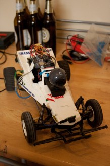
I also mounted a USB webcam on the chassis, for a bit of fun...
I can't quite get embedded video working, so here's a link to a youtube vid I took. I didn't realise quite how dusty my kitchen is, so I apologise for the "mess" - and my naked legs! :) http://www.youtube.com/watch?v=ebfZA0p6FO0
UPDATE 23/09:
Nope, I haven't forgotten about this, it's just been on the back burner! My original post mentioned that I'd ordered some IR sensors already. This was a big fat fib! I planned to order the parts, but never got round to it! As with many of my harebrained schemes, this fell to the wayside for a while - I had always planned to pick it back up again, but just never got round to it...
Originally I'd planned to build sensors myself, but while browsing http://www.active-robots.com for some audio/video transmitters, I stumbled across these little IR sensors, which I did actually bother to order..
Cute, aren't they? They will detect objects between 2 and 10cm away and are nice and cheap; they have no distance measuring capabilities, but I'm not really worried about that yet. Out came the soldering iron to attach the headers, as well as some time consuming (and ever so fun) breadboard wiring.
Time to dig out the arduino and see how awkward the wiring is going to be.
Not too bad at all. The next task was to mount the sensors somewhere on the chassis. There aren't really any points on the chassis that are suitable to mount these sensors. But there's always a solution to every problem - this solution involved one of my favourite tools.
The hot glue gun and I have a long and fruitful relationship... Oh and yes, that is my spidery child-like handwriting in the background there... Once I'd mounted the sensors to the chassis, I mounted the arduino board and the breadboard; once the glue had chance to dry (and I'd taken a break for a cup of tea, some biscuits and a quick smoke), I wired all the sensors up and hooked up the electronic speed controller & steering servo. It's a bit of a mess in there...
The stripboard I wired up for the bump switch implementation was much neater.
Though luckily, I do have some stripboard spare.
But what's that crap soldered to it?
Facepalm. I have no idea why I soldered some battery connectors to stripboard - it's a damned waste of space... Some time over the weekend, I'll get that off there and try to put together a more elegant interface board for the sensors & servos. Though first, I have to go over the Arduino code. I'm pretty happy with the way it works, but I want to slow the speed down a little and tweak it an awful lot more. It still gets stuck against a wall from time to time, so I'm not quite ready to share a video of it yet - plus my kitchen is a little messy, so I need to clean up before I wander round it with a camera!
I'll probably be working on this over the weekend, so I'll try and keep this post up to date. In the mean time, here are some more photos of the sensors mounted on the chassis. I actually need to move the two side sensors; they got knocked off during testing when it was getting stuck against walls... Oops.
Right
Front
Left
Rear
One final shot of the whole thing.
And lastly, here's a link to the current Arduino code: http://pastebin.com/SJvQZiSZ
Original Post (11/01/11):
Well, I thought it was about time I posted some kind of write up about this. I'm also going to be cross-posting this to my blog, but nobody reads that so I'll be coming back here to check for replies & comments! :). Forgive me if I ramble a bit...
A few years ago, I bought a Tamiya Grasshopper RC kit.
It was purely nostalgic, as I'd always wanted one as a kid but never got one. Fast forward several years and it's gathering dust in a closet - as do many of my impulse buys. I had a few ideas about putting on a video camera and hooking up some kind of wireless audio/video transmitter. Then I discovered this site and started reading a little bit more about robotics. I already have a platform and a chassis that works, so all I need to do is replace the radio receiver with a programmable electronic brain and I'll have something you can call a "robot". After a few posts on the forums here (and much passage of time), I took the plunge and bought an Arduino. I know I could have gone with something simpler, like a PICAxe, but I'm a fashion victim.
After some experimentation (and advice from this very site), I managed to figure out how the components were controlled in the existing setup. It's actually really simple: the RC receiver controls the steering servo and electronic speed controller (ESC) using PWM signals. PWM makes my job an awful lot easier. Plus, I don't have to worry about driving the motor from the Arduino - which is good, because the motor is rated for up to 7.2v (although I've used 8.4v with no problem) and sucks down some pretty serious amps. From there, it was a matter of experimenting with different PWM output values from the arduino in order to figure out the range of movement for the steering servo, and the ideal values for the motor output. As this is a pretty nippy RC car, I don't simply want the motor running at full speed all the time; at least not until I'm confident that it can navigate itself around obstacles.
At first, I managed to work out how to get it to drive forward for a specific distance, stop, reverse and turn, then repeat. Except that it wouldn't go into reverse. Working this out involved much head scratching. If I simply set the motor PWM to zero, that will indeed stop the car. But if it then tries to go into reverse, it won't move backwards. After many hours of banging my head against a wall and re-writing my code, I remembered how it worked with the RC control. Because of some bizarre quirk of the speed controller - possibly some kind of "race" mode - you can't just release the throttle and then throw it into reverse. No, first you have to "apply the brakes", then put the throttle to neutral - only after this can you reverse. To "apply the brakes" you have to go straight from forward throttle to full reverse. If the throttle is set to nil, the car rolls to a stop - because of momentum. However if you apply the brakes, it stops dead - no rolling, it stops pretty much instantly. Once I'd figured this out, it started reversing without a problem.
At this point, everything is now controlled by the Arduino. Except that it's completely blind: no sensors at all. I wanted something working *now*, and didn't want to order something online and have to wait for it. That meant fancy ultrasonic or infrared ranging sensors were out of the question - at least temporarily. I have quite a bit of junk lying round, so I started rummaging and scavenging what components I could find. I ripped apart an old computer chassis and found the power & reset switches - these are momentary push-to-make switches. Score! Ideal bump switches! I stuck the switch on to the bumper with some blu-tak (it was permanently glued, once I figured everything out), and started some low-speed experiments. This is when I learned about having to debounce switches - after much more headscratching when the switches didn't work as expected.
At the moment, it's reached the stage where it drives along until it bumps into a wall. When it does so, it stops dead, reverses and turns 90 degrees, then moves off again until it hits something. Obviously this is pretty rudimentary, so some more sophisticated sensors are needed for true obstacle avoidance. After seeing the prices of some IR and ultrasonic proximity sensors, I decided to put this on the back burner until I had a bit more spare cash (I'm a cheapskate, I'm afraid).
The project has remained dormant for a few months, but recently started researching how to make my own IR proximity sensors. I decided that I don't really need range-finding capabilities, so I really don't need something like the GPD12. Plus, is it really that hard to build a sensor myself out of cheap components? After all, IR emitter/receivers are less than 50p each. Looking at this link, I discovered that it does indeed look pretty easy. Pricing up the IR emitter and receiver on Rapid reveals that I can make 5 of these sensors myself for the less than the cost of two GPD12/15's. So, I have 5 Osram LD274-3 IR emitters and 5 Sharp IS471F detectors on order from Rapid.
For now, IR proximity sensors will suffice. Once I'm more confident in my coding I will upgrade to range sensors, rather than simple digital sensors. It is my intention to eventually run the motor at full speed (or close to full speed at least). Using range sensors, I'll be able to better detect when the robot is approaching an obstacle at speed - therefore giving the steering more time to respond. I also intend to mount a small camera and have the video transmitted back wirelessly - I already have a pinhole camera and a small 2.5" LCD, and 2.4Ghz wireless modules look pretty inexpensive.
I see much more development for this little project in the future... In the mean time, here some photos:
UPDATE 09.01.2011:
Link to the Arduino code: http://pastebin.com/8twiQD80
PS, the "Cost to build" includes the original cost of the RC car kit and radio gear.
Navigate using 4x infrared sensors
- Actuators / output devices: servo, Electronic Speed Controller
- Control method: autonomous
- CPU: Arduino Duemilanove
- Power source: 7.2v Racing Pack
- Programming language: Wiring (Arduino)
- Sensors / input devices: bumper switch
- Target environment: indoor, possibly outdoor