


Ar-Du
Ar-Du is finally finished.
The block diagram:
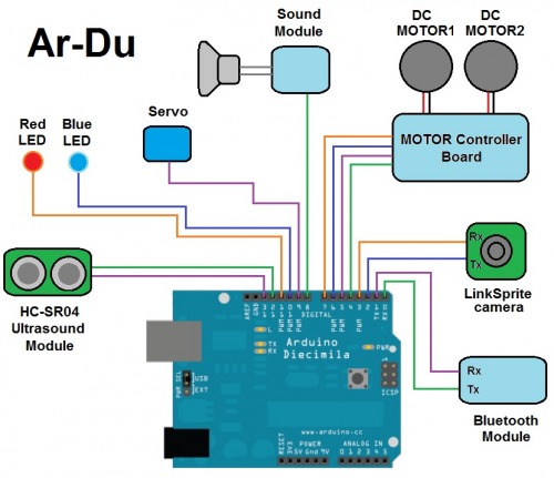
Digital I/O PINs:
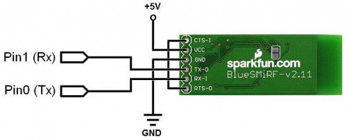
Pin0 (Rx) : BT module Tx Pin
Pin1 (Tx) : BT module Rx Pin
Pin2 : NewSoftSerial Rx – JPEG camera Tx
Pin3 : NewSoftSerial Tx – JPEG camera Rx
Pin4 : Motor1 diredtion select
Pin5 : Motor1 speed (PWM)
Pin6 : Motor2 speed (PWM)
Pin7 : Motor2 diredtion select
Pin8 : Sound Module
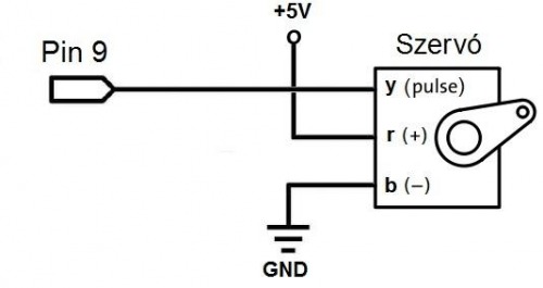
Pin9 : Head rotating servo
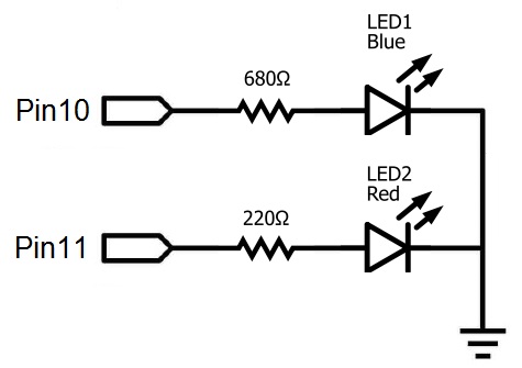
Pin10 : Blue LED
Pin11 : Red LED
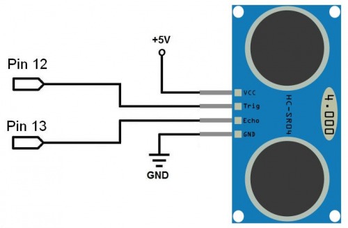
Pin12 : Ultrasound module – Trigger pin
Pin13 : Ultrasound module – Echo pin
Analog PINs:
Analog0 : –
Analog1 : –
Analog2 : –
Analog3 : –
Analog4 : –
Analog5 : –
The main components include the following:
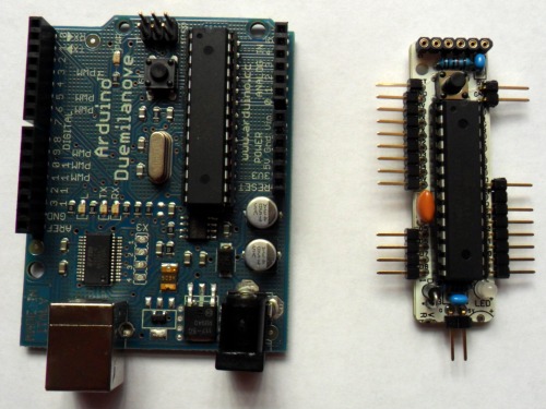
- First I wanted to use an Arduino board, but it could not fit into Ar-Du. Than I changed the to a much smaller RBBB board.
- a BlueSmirf Bluetooth module
- a LinkSprite serial camera
![]()
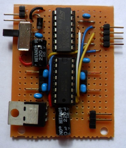
- a DC motor controller board (based on a L293D and a hex inverter IC)
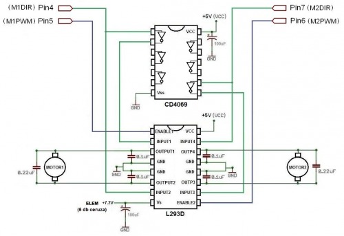
The Motor controller assembled on a proto board:
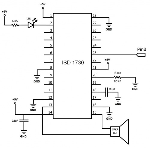
- a Sound Module based on an ISD 1730 IC (this circuit is for playback only to reduce space, otherwise it would not fit into Ar-Du).
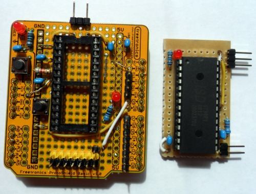
The first version of the Sound module was assembled on an Arduino protoshield, but it was too large to fit into the robot. The second version is much smaller...
I have created a sound sample on http://www.r2d2translator.com
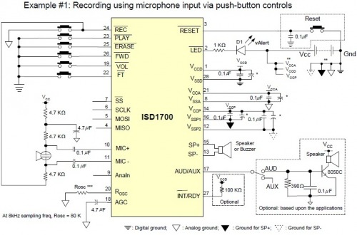
To record the sound sample, temporarly I have assembled the following circuit on a breadboard (source: ISD1700 datasheet):
- a HC-SR04 ultrasonic sensor
- a hobby microservo
- a Blue and a Red LED
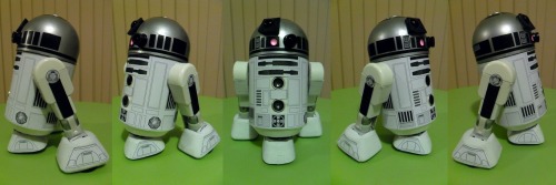
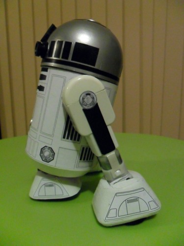
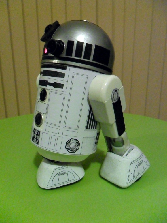
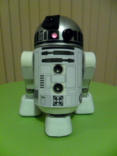
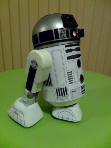
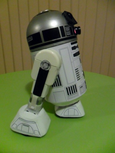
This is how it looks like fully assembled:
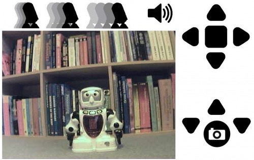
Here is a sample picture of the control interface:
I have attached the Arduino and the Processing codes.
Bluetooth remote controlled robot capable of taking pictures
- Actuators / output devices: solarbotics gear motors
- Control method: Bluetooth remote controlled
- CPU: Arduino Duemilanove
- Operating system: Windows 7
- Power source: 6 AA batteries
- Programming language: Arduino, Processing
- Sensors / input devices: HC-SR04 ultrasonic sensor, LinkSprite serial camera
- Target environment: indoors