


APM 2.5 Ardurover GPS Guided Robot
After seering that many people like making their rc quad-copters/ helicopters and planes autonomous by use of gps guided flight controllers, i throught i would try making an autonomous rover since not many people make some. For my application, i used an Ardupilot 2.5. (re-branded as the "HK pilot Mega" by hobbyking which based on the same chip that is at the heart of the arduino mega 2560. It is also configured for use on rc boats and rc cars.I purchased the parts from numerous vendors but on a good day you can find all the parts in stock at Hobbyking purchasing from numerous vendors ended up with me spending $190. If it had all been purchased at hobbyking it would have cost me $126.50. I would have made a huge saving.
Here is the parts list and how much it cost: I have also included the other online stores that you can buy the items that are out of stock at Hobbyking (keep in mind that these Online stores are australian stores, except for hobbyking which is global.)
This project is on-going so please keep an eye out on updates.
I highly recommend purchasing items from hobbyking as they have nearly all the parts you need ato buy to make a robot. They even have a section mainly for arduino robotics. They have batteries, battery conectors, cables, arduino boards, geared motors, robot chassis,tools....The list goes on.
Item, cost and store:
HK pilot mega 2.5 X1 $75 Hobbyking
http://www.hobbyking.com/hobbyking/store/__37328__hkpilot_mega_v2_5_flight_controller_usb_gyro_acc_mag_baro.html
Hk pilot mega case X1 $11 Mongrel gear(Australia)
http://www.mongrelgear.com.au/flight-controllers/apm2-5-case-top-entry-detail.html
You can buy the case from hobbyking for $5.55 but it is out of stock at the moment.
http://www.hobbyking.com/hobbyking/store/__29650__Turnigy_Mounting_Box_for_HKPilot_Mega_V2_5_Flight_Controller.html?strSearch=hk%20pilot
Neo Ublox gps module x1 $45 Mongrel gear(Australia)
http://www.mongrelgear.com.au/rc-timer-products/u-blox-cn-06-gps-v2-detail.html
The same one is on sale on hobbyking for $18 (if you manage to find it in stock.)
http://www.hobbyking.com/hobbyking/store/__31135__NEO_6M_GPS_Module.html
Apm power cable with xt60connectors $29 Uav robotics (Australia)
http://www.uavrobotics.com.au/power-module-with-xt60-connectors-p-109.html
The same cable can be purchased from hobbyking for $17.99(again if you manage to find it in stock)
http://www.hobbyking.com/hobbyking/store/__31135__NEO_6M_GPS_Module.html
The motors are generic rs540sh 37mm 500rpm geared motors purchased from ebay 2 years ago for $15 each. They pack lots of power and endless torque for my project but the downside is that they have a rediculously high stall current of 42A. each For my project they are overkill but i tend to prefer to use what i have got. These ones i retained from my surveillance robot. They worked quite well. and were able to achieve a speed of 11.5km/h with the DAGU Wild thumper wheels i had on it.
The wheels are also generic 1:10 scale rc car wheels about 130mm in diameter. They have a sponge in between the the tyre and the rim which makes it easier to travel offroad. They were purchased from a friend for $20. They can be purchased for about $28 on ebay.
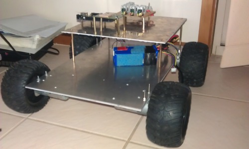
The chassis. I decided to go as cheap as i could on this one. I Simply mounted my motors on a 4mm aluminium plate. and all the components will be mounted on the top "shelf" on standoffs and under it as well. I noticed that almost all open source robot kits had the same approach of having motors at the bottom and having a multi layered body where the componets will be attached, so i decided to follow that approach.
Batteries:
I also decided on re-using the batteries i had left over from the surveillance rover robot. The batteries are 2200mah 3 cell lithium polymer batteries 12.6v fully charged. I have 2 of them in parallel to 4400 mah. In terms of run time, from my previous robot, i got about 2 hous maximum on a good day before battery levels got to the minimum voltage of 3.7v per cell.
Electronic speed control:
Finding electronic speed controllers for my motors that meet the required voltage and current rating without spending too much money is difficult, especially when you are trying to avoid cheap generic ones on ebay. For me i have had a great experience with the so called 320a brushed esc. They are more like 40 amp at best but they peform very well. With the surveillance robot i had one speed controller controlling two motors with no issues but now i have decided to have 4 motor controllers, one per motor just to remove the stress on the motor controllers and to be on the safe side.
Build progress:
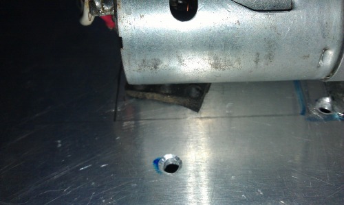
Marking out and drilling the holes for the mounts i used m3 nuts and screws.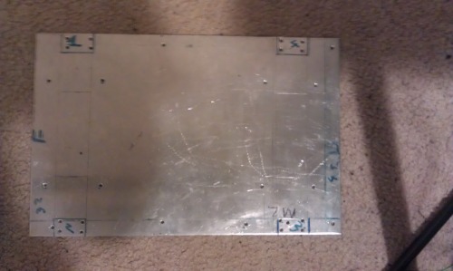
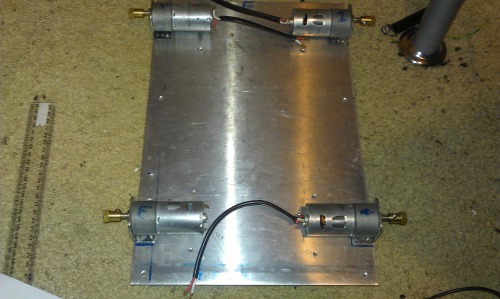
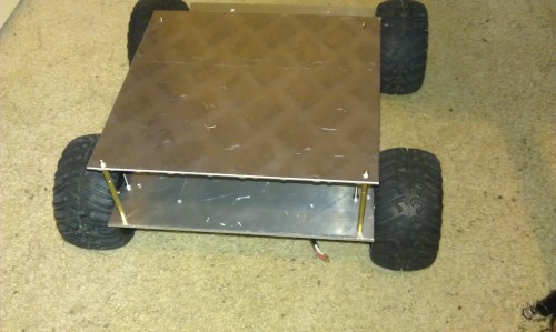
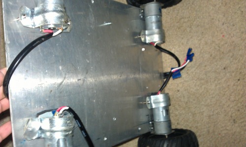
The 4 big motors mounted with their mounts on the chassis.They were mounted underneath for better ground clearance.
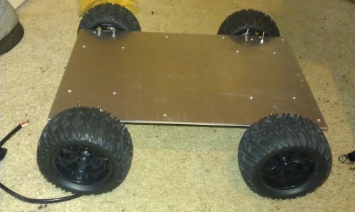
The wheels now mounted. I get about100mm ground clearence.
You can see how they are mounted at the bottom of the plate. I will add some extra mounts to hold the back end of the motors
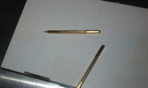
I used 1 40mm and 2 20mm to create an 80mm standoff These are going to be used for the top shelf.
The standoffs mounted.
I will update as i go so stay tuned!
UPDATE #2
I was busy all week with schoolwork so i did not get much of a chance to update. However i received some components i purchased over the net.
My Gps module, my APM power module cable arrived and a lovely set of drill bits to help me along the way also showed up.
Today i managed to mount some of my components on to the chassis:
ESC Motor controller cooling setup:
As you can see below i have 2 40mm fans bolted onto the box that i will use to secure my motor controllers. they are bound to get hot, and these fan's airflow is adequate enough to keep them at a good oprating temperature. To save power, i will control these fans either by Arduino and the DHT11 temperature sensor, or by use of a Normally Open Temperature switch, which when the temperature reaches 45 degrees, the fans will turn on and cool down the esc's.
Monster Voltage Regulator Module.
I call this the Monster Voltage Regulator Module as is supplies 6v, 3.3V and 5v to sensors servos and microprocessors. The 6v regulator array supplies 4A to the servos for my soon to be implemented robotic arm or my pan and tilt wireless camera setup. the 3.3v regulator supplies 800ma to any future 3.3v sensors. The 5v regulator array supplies 2A to any sensors or microprocessors requiring 5v.This will be come more useful when i start using the completed robot for e.g gathering terrain data, temperature readings e.tc. The whole module cost me about $15 to build.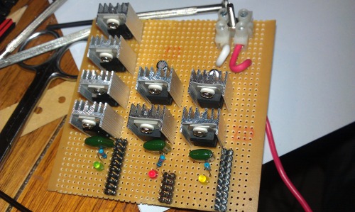
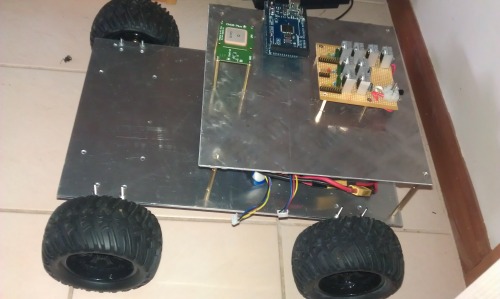
Here are all the Photos from today's update. The mounted GPS Module,Arduino Mega and The Voltage regulator module
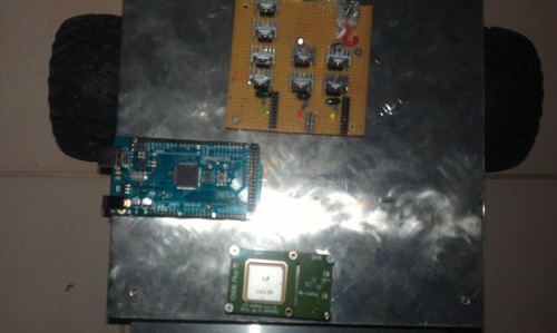
Front View
Top View
Stay Tuned!.
Update #3
Its been a while since i have worked on this machine (5 months to be exact). I have been too busy with University and i am back with some big plans. The testing of the 4 ESC'S has gone well and i have decided to place the esc's in a bigger box and put in a 125mm fan instead. It is a 5v fan and its silent and produces more air flow and draws a lot less power than the 2 40mm fans put together. I am thinking on having a case 3d- printed for the esc's.
Stay Tuned for more!
Update #4
I uploaded a video showing the testing of the chassis. The rover handles unmowed grass very well. As you can see it can also go over obstacles as shown in the second video. Traction isnt as bad as i thought it would be. In this video i was also testing the platform looking for some issues so far the only issues were bolts that connect the wheel to the hub were coming un-done and the mounts need some supports to prevent them from bending., hence the slightly erratic driving :)
Update #5
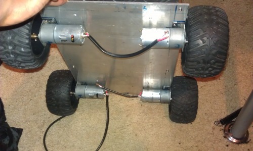
I was able to attach extra motor mounts at the back to prevent the main ones from breaking. This made the power train more sturdy, i have used these in my previous robots and they have worked well. You might notice a rubber pad between the motor and the chassis, this is to dampen the noise and reduce the vibrations of the motor that may interfere with the sensitive components of the Ardupilot autopilot.
Here is one up close fully done: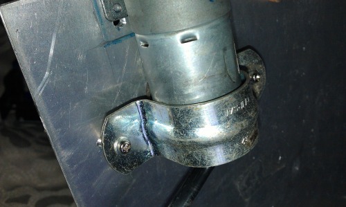
All 4 of them:
Stay Tuned for more!
UPdate #6
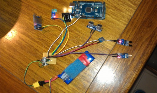
A view of the autonomous hardware that is going to be implemented shortly:
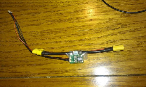
The APM Power module: powers the the brains of the robot.
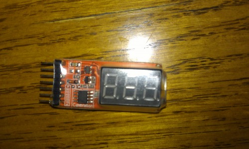
The battery meter/alert module to let me know when the voltage is low. This one tells me the overall battery voltage and the voltage in each cell. it can measure up to 6 cells. You can buy this on Ebay relatively cheap but they are not too acurate but they get the job done.
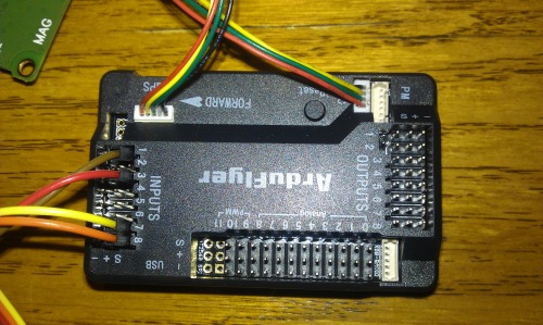
The APM 2.5 "the brain" based on the arduino mega 2560.
The gps module

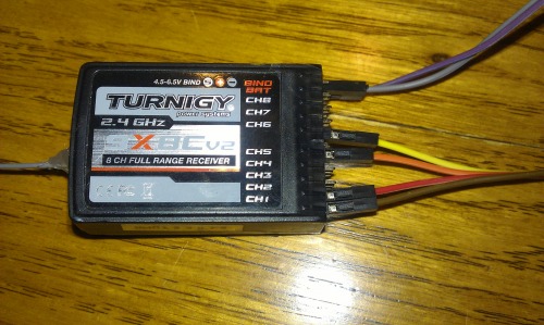
The 8 channel receiver:
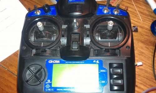
The transmitter to be used. The turnigy 9X, recommended to be purchased from Hobbyking.com
The Software:
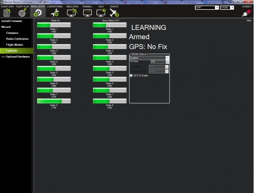
The next 2 photos are showing the adjusting and assigning channels to the APM2.5
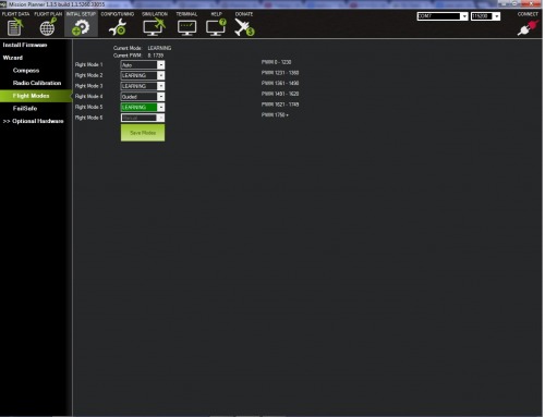
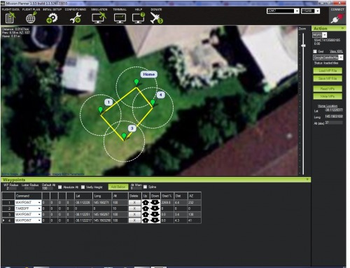
Planning a mission!
After i wired everything up, i then started tinkering with the software (Mission Planner) I was able to make a mock course before i could tests it, i realised that it was dark out! I will connect everything on the rover and test the course in the next 2 days! wish me luck!
Stay Tuned for more!
Update #7
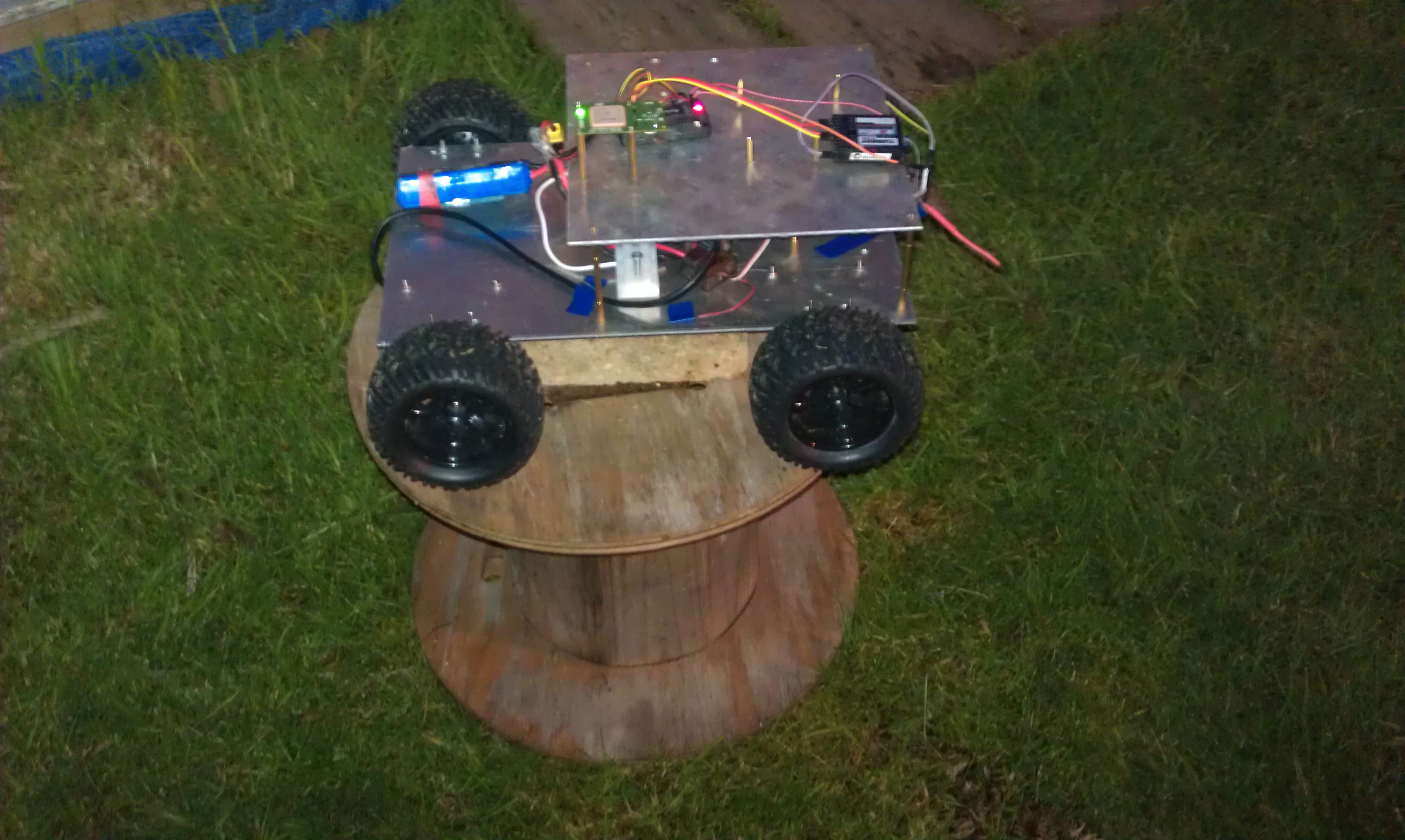
I connected the electronic components to the chassis and i have to admit i was rather nervous to switch it on, as the rover can be quite twitchy because of the high torque levels the motors have and i did not want to crash it and possibly ruin the gearboxes of the motors. I couldnt do a proper/ full test as it was dark outside. I placed the rover's mid section on top of some bricks and a wooden seat so i can observe its behaviour when i powered it up.
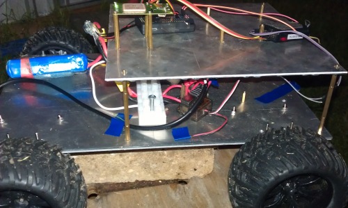
Everything is taped up just for testing so that i can quickly make fixes/adjustments, thats why it looks so messy :)
When i switched the transmitter, all motors remained off and when i flicked CH7 (which makes it follow the pre-programmed waypoints) all motors started spinning forward. upon lifting it and orienting it in different directions, the motors responded by changing speed and reversing depending on the direction. SUCCESS! the GPS and compass do respond to changes in direction, which was my biggest doubt. I will test it again tomorrow, this time using my slower wiper motor powered chassis so that i can easily catch it, make adjustments and then transfer it to my Ardurover. I should really give it a name!
Stay Tuned!
Update #8
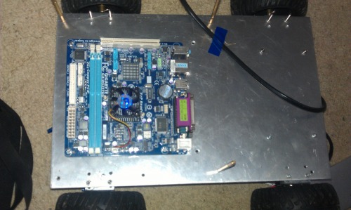
I bought a mini itx board to incoporate into my robot and for my soon to be "Mobile Facial Recognition Robot" running opencv. The board is quite small but powerful measuring only 17x 17x 4cm high! I thought i would implement it onto this robot and program my waypoints without the need for carrying a laptop. i also plan on making it a telepresence robot. (In other words i will be able to control it from anywhere around the world! Perfect for security and checking on your house, or even use it to terrorise family pets while at work or away.
The spec of the board is as follows
CPU: Atom D525 Dual core 1.80Ghz (Hyperthreaded)
RAM: DDR3 2 DIM's (4gb DDR3 1333MHz installed)
4x usb 2.0 Ports
4x SATA Ports/connectors
PCI Slot
Ethernet port
A link to all the spec:
http://www.gigabyte.com.au/products/product-page.aspx?pid=3549#ov
At $50 on ebay, Its a bargain also considering that i already had the ram, keyboard and mouse! I will have to buy a 12v psu for it. They are quite pricy at $23 each
I have seen many people using raspberry pi's PC-Duinos, Beaglebones to do facial recognition/e.t.c But i wanted something more powerful and customizable and also i am very familiar with windows. The board will be communicating with an arduino board to control it via telepresence. But thats for later!
Some photos showing the board
Still in its wrapper :) !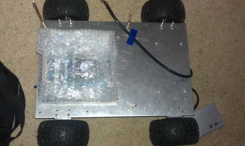
It will fit perfectly on to my rover with plenty of space to spare. I will have to add another plate to make it 3 Tier robot.
Update #9
I seem to have hit a wall. When i tested the rover and it was just going around in circles, not even driving towards the waypoints. I then joined the DIY drones website and they told me to make my waypoints longer than 5m. I will be doing that some time tomorrow. At the moment i am much aquainted with the mini itx that i bought!
Update #9.5
After i installed windows on my mini itx, as usual, after a fresh intall, one has to endure downloading and installing 300+MB worth of updates. Making the most of my time, i ducked out just before it went dark and while the updates were installing and sorted out my waypoints and Voila! The rover followed the waypoints! The only problem i had is the turn radius that i need to adjust. The rover would overshoot the waypoint, get confused and then reverse-go forward and jitter all over the place. I will sort out this tomorrow and we might have a working autonomous rover by the weekend!
Update #10.
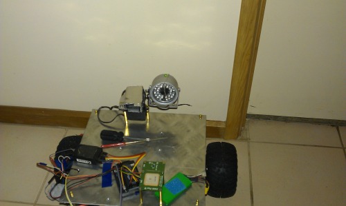
I made a pan and tilt system for my rover using 2 servos and a bit of left over sheet metal. Its a very simple design and it works very well. have uploaded a video of it working powered by my homemade 6v regulator board.
Update #11
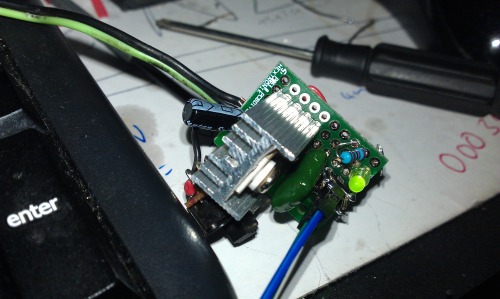
I made some power supply modules to power up servos for the pan and tilt system and the arduino-run sensors. The servo power supply has an LM7806 6V regulator rated at 1.5A and the sensor/Arduino voltage regulator is an LM7805 rated at 1A.
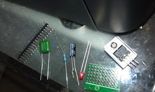
The components used to make the 6V power supply:
-LM7806
-Heatsink
0.47microFarad Capacitor x1
0.1 microFarad Capacitor x1
Power indicator led x1
300 ohm resistor x1
header pins x6
small breadboard x1
and a switch
End result :)
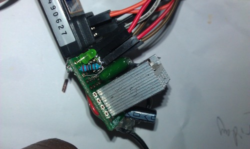
All ready for Testing!

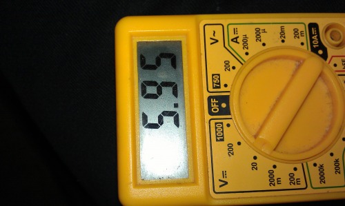
Led Indicates that power is on. I will later mount it on standoffs. The power supply can supply a radio receiver and 2 servo motors. The voltage regulator did not get hot at all during operation.
5.95V out. Not bad!
The 5V regulator module.
I cut out part of my Big regulator module since you can not parallel voltage regulators. It has room for 10 components. I will be running a fair amount of sensors to gather data for my sd card module!
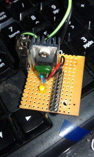
8 components connected with room for 2 more!

4.96-4.97v out.
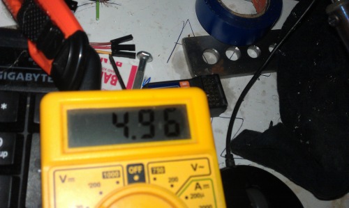
SD card module, current sensor, colour sensor, arduiono Mega, The faithful HCSRO4, Fire sensor and light sensor being powered up by the voltage regulator. The regulator got a tad warm but i will not be running all of them at once.
Stay tuned!
Update #12
The Wireless Camera System
To monitor the robot when it is no longer in line of sight, I salvaged this wireless camera/receiver system from my year 12 Final year project. It has a range of 50m, using an 8.4v battery and i would get better range if i was using a 12v battery. The Camera has a set of 5mm night vision IR's that work really well although i don't think you need 32 of them! Current draw is around 120mA but it would be alot more with night vision turned on. The night vision IR's are activated by a Light Dependent Resistor/LDR.
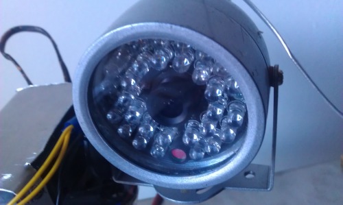
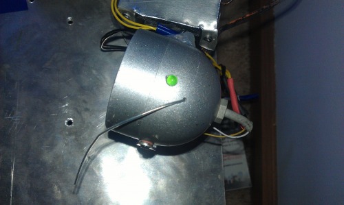
As you can see i performed a little "hack" of my own to get the camera to tell me when it is on, to make fault finding easier!
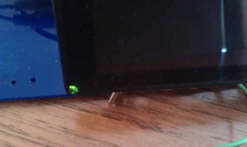
The Viewing Screen
The monitor is a 4.3 inch model i bought from eBay 3 years ago. It was a bit pricey at $45 but you can now get 7 inch models for a lot cheaper ~$30. Current draw (measured) is around 100mA and unfortunately does not come with a speaker.
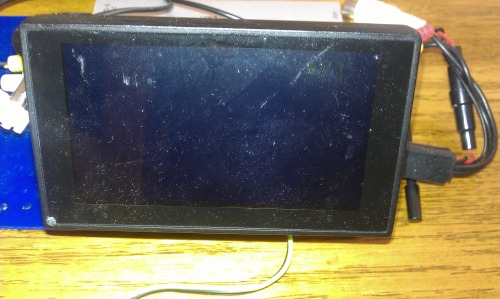
As you can see again, i have inserted an LED to tell me when the screen is getting power.
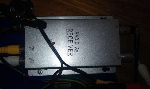
The receiver
The system is a 2.4 ghz system and as great range. There is no inteference with internet signals and you can also get an rca to usb connection direct from the receiver to the laptop/computer incase you don't want to purchase another monitor.
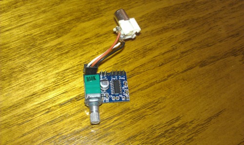
The Sound Module.
Since the monitor does not come with sound capability, i bought a sound module, they are very cheap at about a dollar each. They run on 5v and as you can see mine is jury-rigged to work with an rca audio connection.
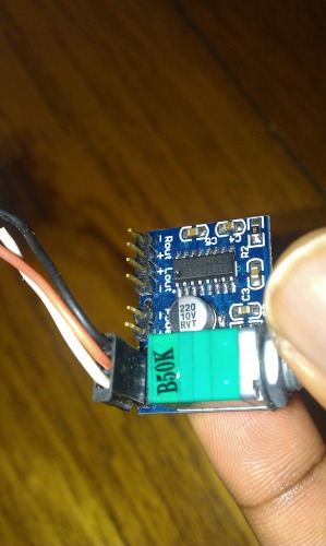
Another view
Because of the weather i can't test my rover so i am inside the house working on features like this. The winds are too high and there are showers ecery now and then. Next i will be working on datalogging!
Stay tuned!
Navigates around Autonomously with pre-programmed waypoints
- Actuators / output devices: 32:1 ratio 500 rpm geared motors
- Control method: Arduino, Autonomous Semi-Autonomous, 2.4ghz radio, or gps guided
- CPU: Apm 2.5 or Ardupilot Mega
- Power source: 2 x 2200mah 3s lipo
- Programming language: C
- Sensors / input devices: ultrasonic sensor, DHT11 temperature sensor
- Target environment: outdoor