


Hexapod Robot Animabot is licensed under a Creative Commons Attribution-NonCommercial-NoDerivatives 4.0 International License.
• Energy: Tenergy Li-Ion 11.1V 7800mAh
• Power Distribution: 3xPTN78020WAH + 1xPTN78060WAH
• Charger: Custom, based on LTC4006-2
• Brain n°1: Raspberry Pi 2 B+
• Brain n°2: STM32F4 Discovery Board
• OS n°1: Raspian
• OS n°2: Chibios RTOS
• Programming Language: C, Python
• Communication: Bluetooth, WiFi
• Vision: Webcam(HD6000) + Led(Luxeon 3W)
• Actuators: 19 Herkulex DRS-0101 digital servomotors
• Control: Autonomous and Remote-controlled
• Sensors: temp(LM35), accelerometer(LIS302DL), power monitor(LTC2945), IR telemeter(GP2Y0A21)
• Target environment: indoor/outdoor
• Weight: 2,2kg
• 3D design: 100%
• 3D printing: 97%
• Mechanical Assembly: 99%
• PCB design: 100%
• PCB fabrication: 100%
• Electronic Assembly: 100%
• Firmware on STM32: 30%
• Firmware on RasPi: 5%
• Applications: 0%
• Stuffs to buy: 100%
>>> Checkout the Interactive 3D model !
All the body is realised on Solidworks and will be fully 3D printed in PLA on my FlashForge Dreamer. The most difficult work was to anticipate during the design, how the boards and the cables will fit inside along with the motors. And also the fixation of the 19 motors inside a body which is about 26x18x9cm.
I will not detail all the steps to get to this result, but fell free to ask me if you have any questions regarding the CAD design.


Animabot's electronic is composed of several PCBs in addition to the RasPi and the STM32:
• Power Supply Board
• Li-Ion Charger
• STM32 Board Adapter
• LED board
• ATXRaspi
• USB audio DAC
All the boards were designed with Altium Designer and made online on SeeedStudio.
Below you can see the architecture of Animabot:

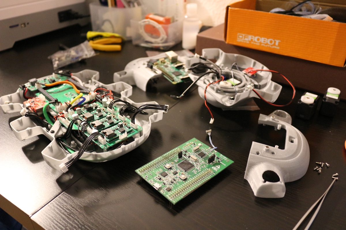
This is the STM32 Adapter. I made this board in order to connect the STM32 to the PowerBoard and the RasPi.

his is the PowerBoard composed of 3xPTN78020WAH + 1xPTN78060WAH switching regulators for powering the servos and the brains. This board is also connected to the STM32 adapter.

This is the Li-Ion charger, certainly the most critical board of Animabot. As I wanted to be able to charge the battery without removing it, I had to make a custom charger based on a LTC4006-2 from Linear Technology.

Voilà ! the boards are finally together ! The power is well distributed to each board, and the "smoke test" is passed. Now I have to create the software on the STM32 discovery board and the mid level since the HAL (Hardware Abstraction Layer) is already provided with Chibios.

3D printing:
All the parts are printed with a Flashforge Dreamer and I use Simplify3D software. To get Animabot printed, it took around 160h of printing for the 44 parts which compose the robot.
Head:
The head in printed in 1 block, from bottom to top in 8h. Inside there is the Webcam(HD6000), the night vision led, active cooling and the servo for the rotation.


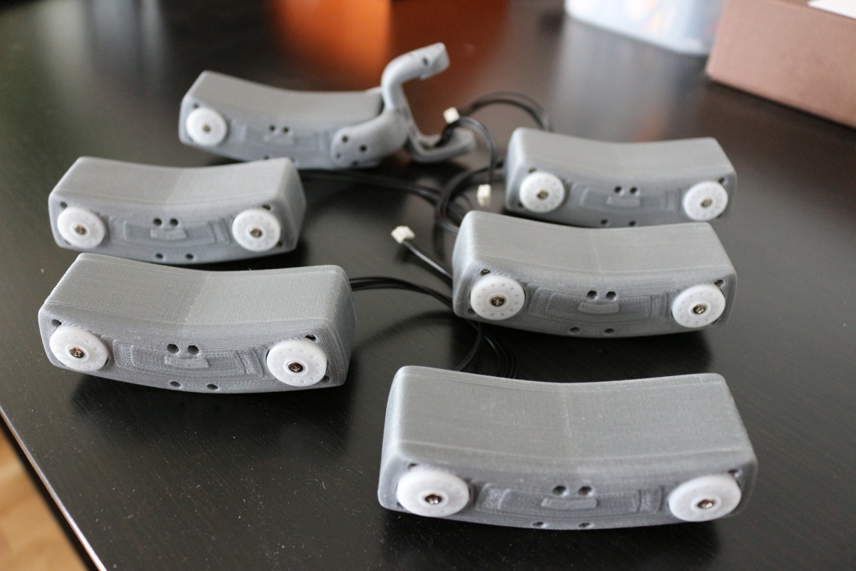
Femur:
The femur is composed of 3 parts: front and back cover + internal shell. The shell is maintained between the 2 covers by 4 small metal rods (Φ1,5 x 30mm).

Tibias:
The tibias are printed in 1 block also (5h each). Then I applied a rubber coat (Plasti Dip) at the end of the tibia to avoid the robot from slipping, as PLA as a very low coefficient of friction.


Lower Body:
The lower body is composed of 5 parts because these parts are too big to be printed in one shot. As you can see below, this is the rear body where are the DC-IN plug, and the interrupters for the Raspi and the battery. The 5 body parts are joined together thanks to a "puzzle shape connector" and some screws. The plate in the center holds these 5 parts together.


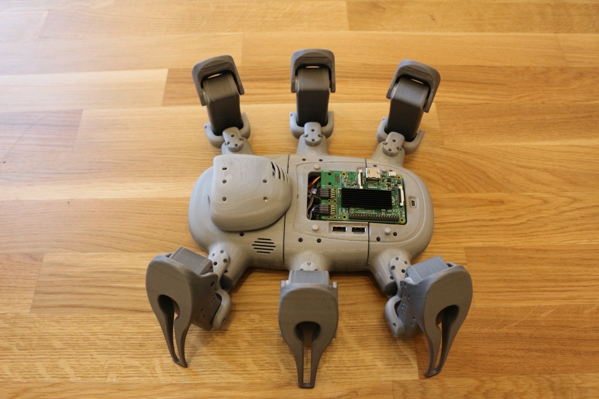
Upper Body:
The upper body is composed of 3 independent parts mounted on the servos and maintained with metal rods to the lower body. The Head is now mounted on the body and functional. The next step is to integrate the speakers and test all the connections inside the robot before crewing all together.


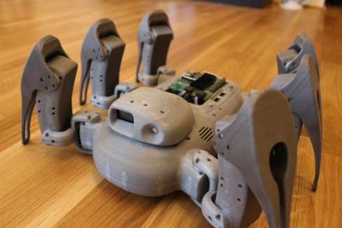
Body Assembly:
Finally after 20 months of design, tests, doubts, bug fix, etc… Animabot is assembled and ready to walk !!!
I had to fix several issues in Anima before mounting the legs and the upper body. First I had to fix the sound problem, curiously the IR sensor was generating noise which was propagated up to the audio amplifier, thus generating audible noise… To fix it I added to capacitors (100nF & 10µF) on the sensor’s power connection. Then I burned the Li-ion charger so I had to replace some mosfet and add some heatsinks.
The body is not as good as I would like it to be, but I think for a first prototype, it's not so bad...


_________________________________________________________________________________________________________________________________________