


ALF - Analog Line Follower
Hi, I am ALF, short for Analog Line Follower. I am not an alien, i do not eat cats and i am pretty much earth based, more precise silicon based ;-)
Ok, this was the self introduction of ALF.
Since some time I am working on a PCB based on a friends circuit plan for an analog line follower. Now the prototype is finished and working (well, the end of the video is staged to give you something to complain ;-) )
There is not much to say, I also do not have much pictures of the build but I will add more later when I am going to adjust the accuracy.
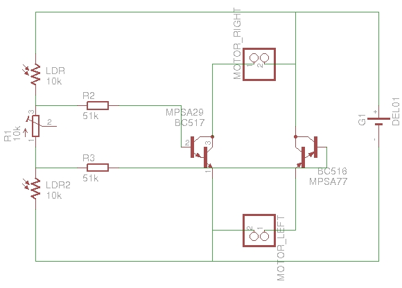
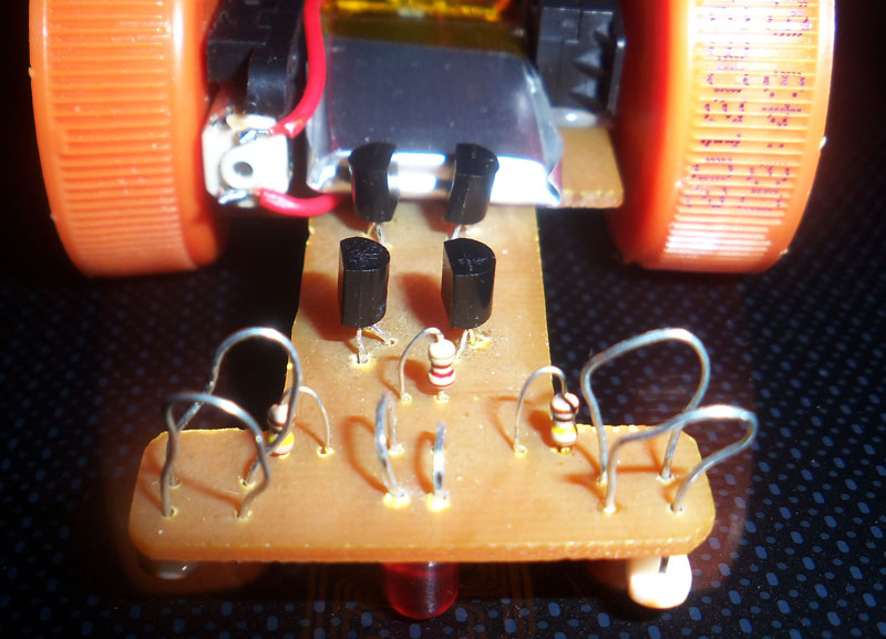
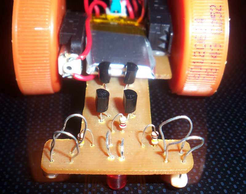
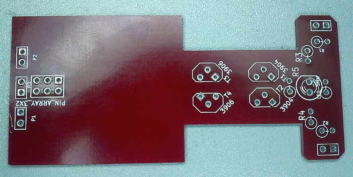
This is the circuit plan my friend designed. For ALF the darlington transistors are replaced with each 3904 and 3906 since they are easier to get here and they are much cheaper.
The PCB was changed some times to find the best way to put all the components on it, balance it and still make it easy to build.
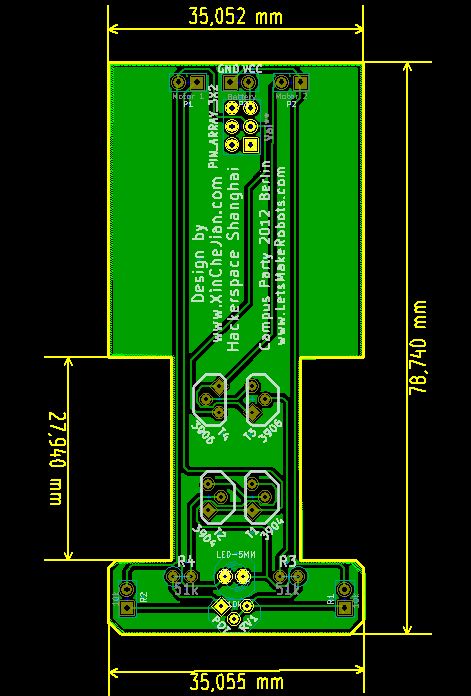
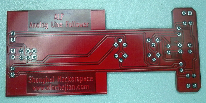
As you can see on the PCB, ALF (or better said the components for at least 100 ALF's) is going to Berlin to the Campus Party and hopefully will be adopted by a lot of people.
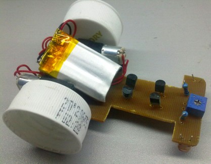
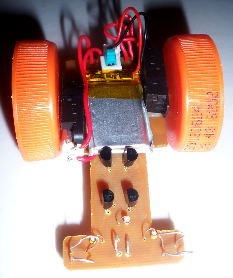
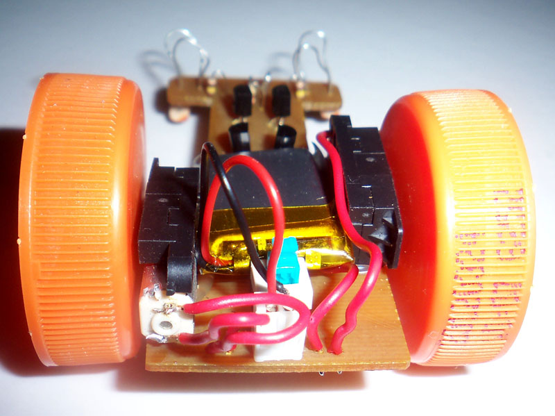
Attaching the gear motors, well, either double side tape or hotglue, what do you think?
The wheels are bottle caps but still need to pull on some tires to get more grip on the surface. This might be rubber band or some cheap foam tires.
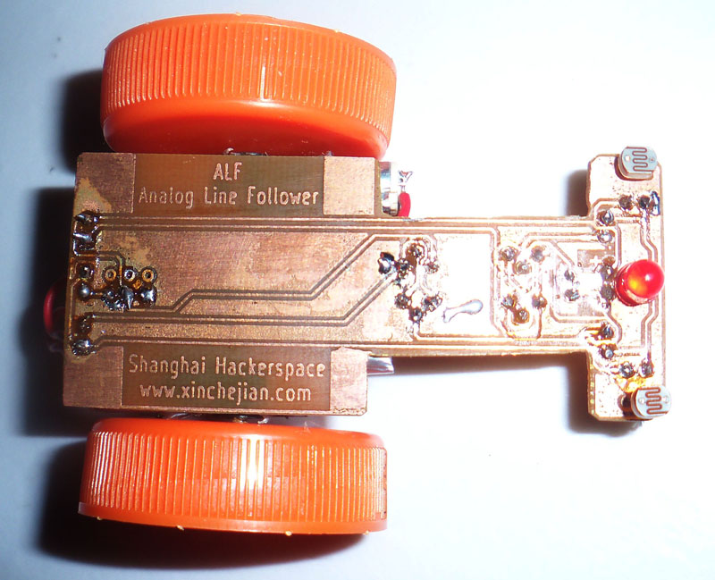
The top view shows you that the PCB still have some rough edges. We will send the files to the factory and hope they will do a better job :-) As I wrote in the beginning...PROTOTYPE :-)
UPDATE July 18:
We had problems with low light conditions. The bot did not want to turn when the light was dimmed. So we changed the LDR's from 10kΩ to 1MΩ. Now it's also working in low light conditions.
Concluson. As the LDR's and the pot build a bridge the potential difference must be big enough to switch the transistors (as bigger the better). 10kΩ LDR's do not have that broad range but 1MΩ have. We measured the following:
10kΩ no light -> 9.6kΩ
10kΩ bright light -> 0.4kΩ
1MΩ no light -> 1.02MΩ
1MΩ bright light 2.7kΩ
This makes a difference of 9.2kΩ for the 10kΩ LDR and more than 1 MΩ for the 1MΩ LDR.
UPDATE July 19:
After changing the LDR to the higher value ALF was running quite good. See the two new videos (unprocessed), One is ALF running on my desk in circles and the other one he is running on ur big racing track with his buddy ALF-M (M for Mosfet).
If you listen carefully then you can hear the kitten in the background...yep, ALF was not eating it ;-)
Why changed 1MΩ LDR?
Ok, here is the thing. We used 10kΩ and it was running well in the free wired robot (no PCB, just direct soldered the components together). This way no light was blocked. Now we upgraded to a PCB and the PCB will block the ambient light so it's basically darker around the LDR now. The potential difference was not big enough to switch the transistors.With a hght value LDR you can get a bigger potential difference, so the robot also runs under dimmed light conditions. Now we even took off the pot and want to try if it's running. The new PCB is etched but no drilling today...
UPDATE July 23:
The new PCB without pot is done and working too. However, I just had 200kΩ LDR's available so I guess the light need to be bright to make this one working good. The test confirmed that. Mybe I will change the LDR's tonight and replace them with 2x 1MΩ to see if I am right. Video, Pictures and more details will come later today.
UPDATE July 24:
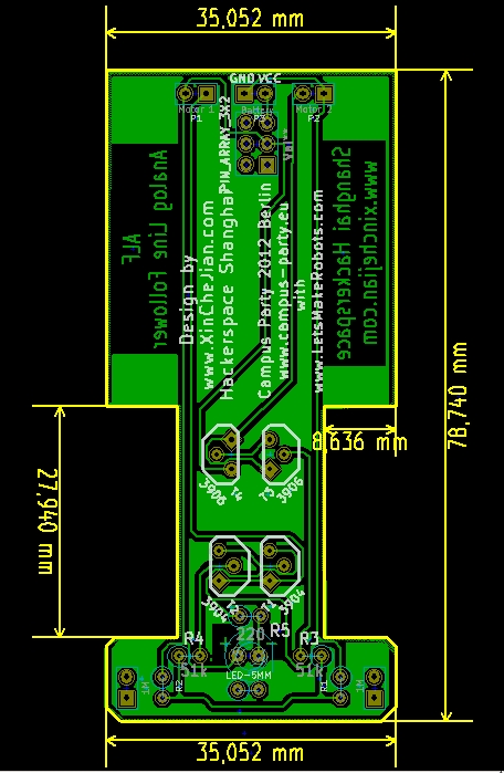
Uploaded a new video showing the Version 2, the one without a trimming pot. It's a habbit to try if it's working with even less components. Also in the video you can see my friends cool design, even smaller and with two MOSFET SMD transistors. Pictures are not done yet, please be patience.
UPDATE July 26:
Basically the robot is finished. We still made another PCB without the trim pot in front and it's working too. Here are some pictures of it.
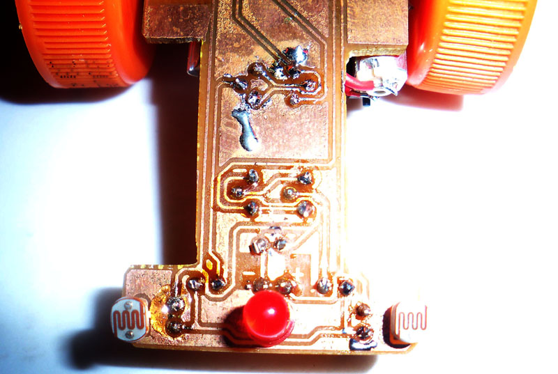
First pic is the new PCB (not much changes, just no pot and then the new attachment for the LDR's and the LED)
Got my boards today, in a nice red finish.
Project done!!!
As a thank you for LMR and it's community please read this.
The ALF prototype board gets retired now. For that he got a photo shooting arranged. Please see the result here.
following a black line
- Actuators / output devices: 2x mini gear motors
- Control method: autonoumous
- CPU: none BEAM
- Operating system: ah...none
- Power source: 1x 3.7V/200mAh LiPo
- Programming language: none
- Sensors / input devices: one pair of LDRs
- Target environment: flat smooth surface with a black line