AGV
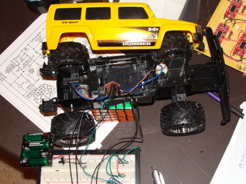
Here is my AGV. It drives to GPS waypoints. It is currently using a Arduino, GPS, and of course a motor controller. The bot itself is a Hummer RC truck from Walmart that i bought for $20. It seems under powered (only runs on 4 AA) but it might be ok as long as it only drives on smooth concrete or smooth roads (my road is no where close to smooth). I have ordered a compass module that should be here Saturday. The compass module will make the navigating a WHOLE lot better. The code right now was written really fast and is as simple as navigation code gets. It steers left or right depending on what it needs to do and measures distance so it knows when it has reached its waypoint. No proportional control in the code right now. I wrote most of this code a while ago but just made it work with the robot today. The code is rusty and so is this post, i had to write the code quickly and make this post quickly because i have school work to do. Will update this post tomorrow or the weekend.
Update 4.27.10
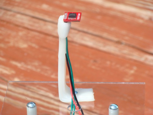
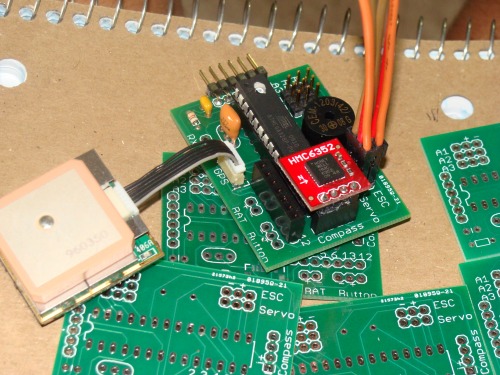
I now have a compass module and i wrote some better code. The compass module is just a life saver. It is really accurate and just makes programming easier. You use i2c to communicate with it and just a snippet of code. Just make sure you mount it level and away from the electronics.
My new code has improved steering. I guess its proportional but i do not know if it is definition proportional drive. I came up with this little formula of delay=degree error / 180 *3000. It takes about 3 secs to turn 180 degrees so 3000 was my number i could tweak. Of course it is out of 180 because that is the most i will be turning either left or right. Our degree of error is how much we are off from our current heading to the heading we need to be at. Simply subtract the current heading from the desired heading and take the absolute value and presto! This code seems to work really well. I tested this in a parking lot plus i had 2 waypoints this time. (see video). You can see the results. the waypoints were given a radius of 2 meters but it normally gets closer than that. I will reduce the radius next time. The AGV is programmed to stop when it reaches its last GPS point. I ordered a l298 motor driver and will update this post when i have that on the AGV and i will have a more complicated path of waypoints.
Update 5.11.10
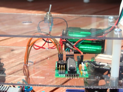
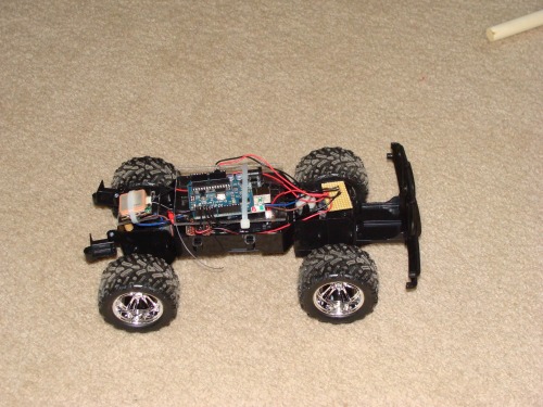
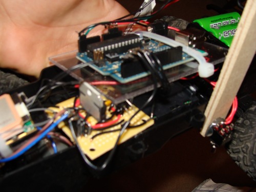
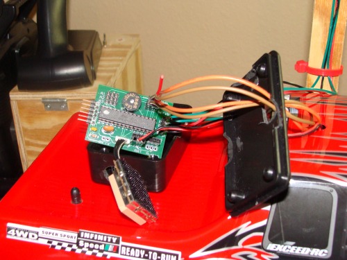
I changed the motor driver to a l298 now which provides more amps to my motors than the l293d did. The front battery pack is now glued down and i have a video of it looping around a retention pond.
The photo is to show my l298 (its not in focus i know)
Update 5.20.10 (see top video)
This idea came to me in math class when i was talking to one of my friends about this robot.
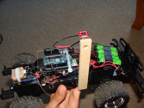
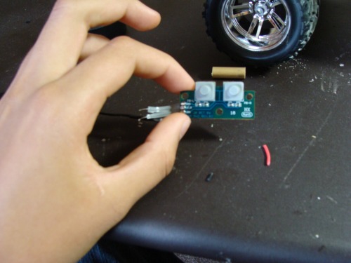
So whats new? BUTTONS!
I added 2 buttons. The one on the right is for storing waypoints. Now all i have to do is push the button and it stores the current location as a waypoint. This is done to store all the waypoints. There is also a LED that lights up to show that it is storing a waypoint. When you are done storing waypoints, then push the left button and the AGV drives the waypoint path. So no more must i lug my laptop around and read the serial monitor, write down the gps points, upload the gps points to the arduino. I now just push these little buttons which i took from a old rc controller from a cheap toy. When i am able to test this at my test site, i will add a better video of it driving in the comments below so be on the look out for it.
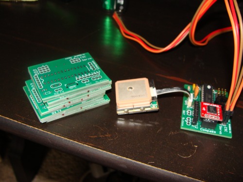
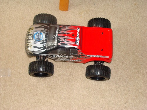
The new RC truck and custom PCBs came on the same day today :) check out the video.
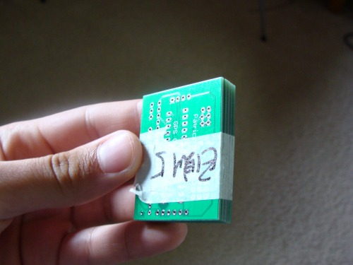
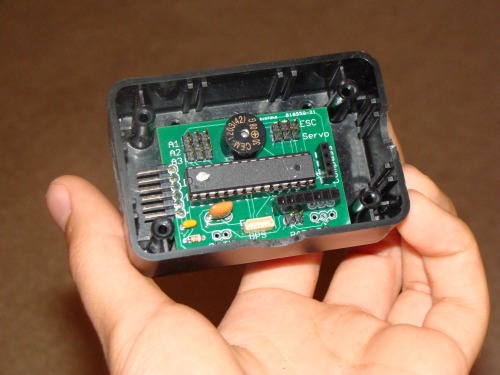
I got the PCBs from Seeedstudio. It took exactly 2 weeks from the day i ordered them to the day they were in my mail box.
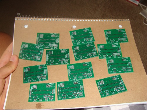
Yeah i soldered one together, even the SMT GPS connector which was not as hard as i thought it would be. It shows you the concept of the board. The Compass and GPS plug right in and there is a place for the ESC and servo. So far i gave it a simple Serial.println("hello world!"); test and it works. On the back of the board is my name and it says "GPS guided Vehicle". I was barely able to squeeze that silk screen on the bottom of the board but it fits.
They E-tested 5 of the boards for free and they are marked and taped together. I am very happy with the boards and the service.
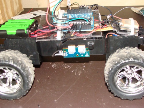
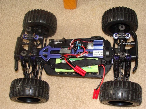
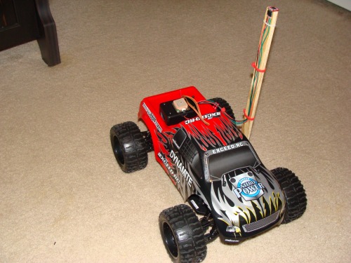
Now on to the truck. Its a big 4WD mean machine.
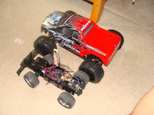
07.03.10
The new truck is completely outfitted with the things needed to be a AGV. I will be working on the code for the next few days. I have ran test code and rough AGV code and my custom board is working fine.
I bought a 3"x 2" x 1" plastic project box from Radio Shack and cut a few different holes for cables to go through. My custom AGV PCB goes inside.
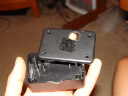
The ESC, servo, and UBEC (regulator) wires go through a hole in the top of the truck that was meant for the antenna.
The box is attached to the bed of the truck using velcro and the GPS is attached to the box using velcro
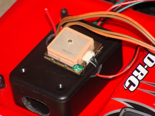
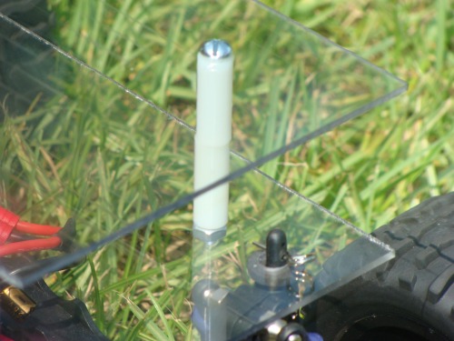
Here it is all finished. Just like before, the compass is mounted high in the air away from any magnetic interference from the electronics and motor.
Update 07.18.10
The hardware is still the same. Only thing different is i added a 4AA battery pack for the board, GPS, and compass.
With lots of help and code from Bill Porter, the code has been redone. It works better and a lot of the un needed things are taken out and bits of code that are more efficient were put in. The code should be running at 10hz. Since the GPS doesnt run at 10hz, the code only goes through the process of getting new GPS data and only updates the distance and heading calculations when there is GPS data available. The reason behind running at 10 hz is so the robot runs its PD calculations and makes its adjustments quickly. The code has been broken down to just a few functions. Where in the main loop it gets new compass data, checks if there is new gps data (if there is new gps data then it runs the bearing and distance calculations), and then executes the PD control. The PD code was given to me by Bill (along with other parts), the output of the PD control is mapped to the output of the Servo so there is no need to determine which way to turn because the mapped values serve that function. Another great bit of code that i wanted was the ability to use the Ardupilot config tool. Its the computer application that they use for uploading waypoints to EEPROM. Its a nice little application where you simply click on the points in the application's google maps window and upload them as waypoints to EEPROM, Bill provided me with this code and it works like a charm.
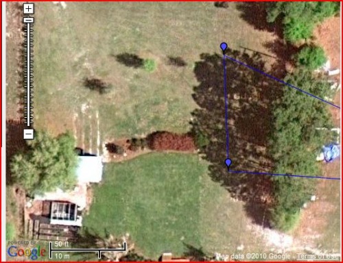
There is video of the successful mission up and feel free to look at the new code in the file attachments, its called "New_AGV.pde".
Here is the 2 waypoint mission you can see in the video
Update 07.22.10
A few tweaks in the PD gains plus i am now controlling the speed of the vehicle manually. Manual control over the vehicle's speed makes it a lot safer to test. For manual speed control i simply unplugged the ESC from my arduino and plugged it into the onboard receiver that the truck came with. You can see the test from today in the videos.
Update 08.22.10
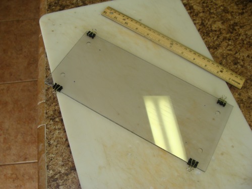
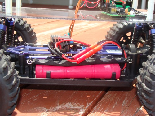
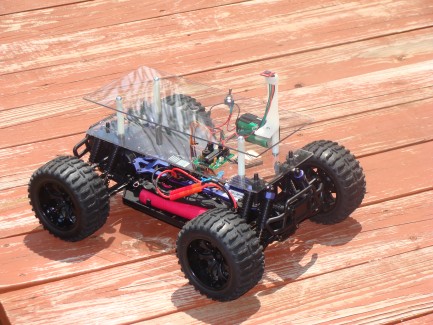
The chassis has changed.
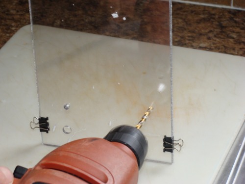
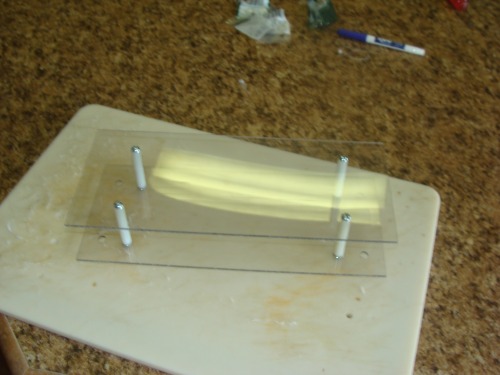
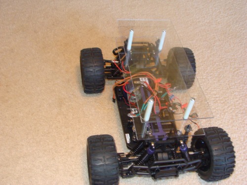
I took that plastic truck shell off of the vehicle because it was pretty useless when it comes to mounting things on it. I decided a dual platform would be perfect for holding a bunch of actuators, sensors, and any thing i want to test.
Leave a comment if you have a idea for what i can add on to it to make it useful / cool.
So here it is: (i think its pretty self explanatory)