A self-balancing robot
So here we are :) I decided to try and build the holy grail of robotics hobbist: a self balancing robot.
I've made some research around and i've come to the conclusion that it should be feasible. The most difficult part is probably going to be the programming, but i'm a computer programmer (quite skilled, btw :P) and i've already have some ideas on how to build it. I worked on some videogames in the past and i have a background on 3D math and physics that should help a lot.
I don't know if it will work, in the worst case i'll use the parts to make a standard non balancing robot :)
Now for the hardware i've choosen:
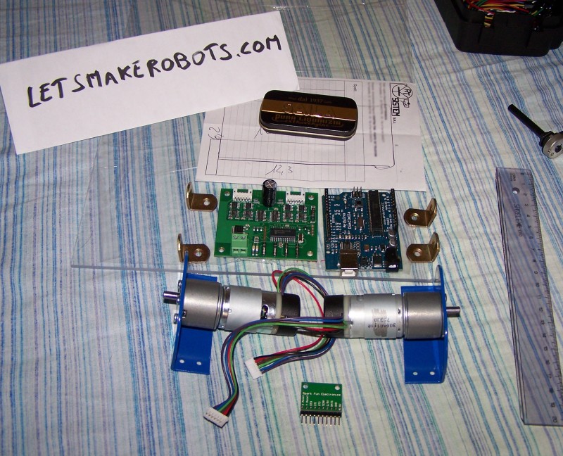
- Main board: Arduino Diecimila. I have a picaxe at home but i think i'll need some more power and memory, and also a more expressive language. I don't want to program a balancing algorithm without variables and floating point math :) Also, the arduino have two regulated output and many other goodies, and it's also Open Source and Italian :)
- IMU sensors: Sparkfun IMU Combo Board - 2 DOF - ADXL203/ADXRS401. This is a combo Gyro/2-axis-acelerometer. Of the many combinations avaiable, i've choosen the one with smaller range but better precision, as i think it's more important in fine balancing. I'd like to have something that is stable and not swinging back and forth.
- Engine: A kit composed of 2 EMG30 12V 170rpm motors with encoders and a MD23 motor controller. The controller can spin the motors at different speeds and has already input and logic for the encoders.
- Battery: i don't know yet, either a motorcycle battery if i can find a cheap one, or some (a lot of :P) standard rechargeable cells.
Ok, now building the robot should be the easy part. I'll use some sheet of pvc or similar to build the structure. The motors come with a support that can easily be attached. I plan to make it quite tall and heavy as it's better for balancing porpouse.
For the software, here's what i've understood about it :P
The inputs are gonna be:
- The rate gyro: it will tell if the robot is rotating. If it's 0, then the robot is not rotating, that is: it's perfectly still, or going in one direction with some fixed speed keeping balanced. It doesn't say anything about where is up and where is down.
- The accelerometer X axis tells if the robot is accelerating forward or backward. It can possibly be used to understand which way are we running or as a dumping factor when the robot change direction (need some actual testing). It will be influenced by the gravity when not parallel to ground.
- The accelerometer Y axis should be able to tell where is up and where is down, since it will be influenced mainly by gravity. It will be influenced by the robot acceleration when not perpendicular to ground, but i should be able to use X acceleration to correct the reading.
- The wheels encoders: they will tell how fast the wheels are spinning so it's the velocity of the robot.
I'm actually studing some kind of filters for the readings if i find they're too noisy.
The algorithm should take this readings and try to solve so that the rotation rate stays at minimum, while the wheel speed at the desired value. The teory is relatively simple but it probably will all be a nightmare of hand-tuned coefficients and such :) I'm planning to put some potentiometers (sorry fritsl, i mean some turn-knob-thingeys) directly on the robot for faster testing. I also have a spare lcd display that could attach to help runtime debugging :)
Ok, for now i've ordered the IMU and the arduino board so i can start some actual testing, the second purchase will be the wheels/motor/controller kit.
So stay tuned for some funky balancing :P
PS any hint or suggestion is of course welcome!
UPDATE 27/08/2008
Here we are :) As you've read on my blog entries, some weeks ago the first bunch of parts has arrived, and i began some testing. One of the first lesson that i've learned on the IMU sensor is that the readings are very noisy when subject vibrations and shaking, even on axes where it should not be sensing. The second thing i learned is that using a kalman filter is not optional.. You need it, there's probably nothing simpler that you can implement to make a precise enough measurement. So i rolled up my sleeves and went down on learning it :)
I've found a couple of particulary useful links that you can find on my blog entry. One has an implementation of it in plain C, the other is for Arduino, the platform i used :P So i must admit, i made some copy/pasting of someone else code (but as someone said long ago: "if i looked that far is becouse i was standing on the shoulders of giants"). Unluckly, some understanding of the code was necessary to adapt it, since he was using a totally different set of sensors, with different ranges and sensitivity. So while the mathematical innards of the kalman filter are still obscure to me, i've come to a good understanding on how to use it and feed it with data.
The hardest part was tuning the values, for example converting the raw gyro reading to a clean "rad/sec" value, or finding out how to put the two accelerometer values on the "atan2" function to obtain a meaningful angle. Indeed, my first try had a problem with the gyro, i was converting the value in the wrong way. The result was still correct, but the system had a real long adaptation time, so that the final angle was updating with about a second delay (making it unuseful for any balancing porpouse). Of course, since i didn't understand the problem, i tried to correct by changing other parameters around and ended up with a Real Mess :) So i decided to clean up everything an finally found out the problem. When i saw the arrow on my PC screen keeping the very same direction of my board, i had some satisfaction :) Now my code is working ok, even if there's probably room for more optimization.
So when i got it, i was looking forward to try it, so i took a wooden stick and attached some components: my arduino, my two GM9 motors, a breadboard with the L293D IC, a mess of sparkfuns premium wires and of course the IMU sensor. This setup is far from optimal, since the GM9 are too slow and the L293D doesn't let you specify a speed (just forward, backward or stop), but i was hoping to see some correct behaviour, ie: the wheels turning on the right direction at the right time. And indeed it was :) It even did real balancing for some brief time! Of course the L293D usually gave too much movement when some very slight correction was needed, and then was too slow to catch up when the stick started falling badly. But i'm almost sure that with the hardware i designed (the RD01) it should work like a charm :) I'll be able to give a speed proportional to the angle.
I took a small video of the stick, unluckly this is not the best balancing it did, but it should give the idea.
Now that i'm almost sure it works, i can finally order my RD01 and purchase my 12V battery :)
Stay tuned for some more balancing :)
UPDATE 08/09/2008
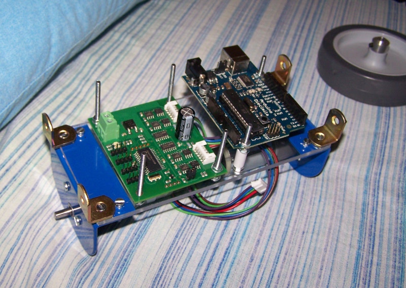
Hello :) So my RD01 base arrived Saturday morning! I had some very hard time making it work, i almost spent all the weekend but finally i managed to control the MD23 board with my arduino! I also made some preliminary design and hacked together a base for the robot. Here's some pictures :)
UPDATE 28/09/2008
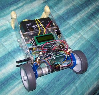
Yayyy! Something works, i can't believe it :) I'm so proud and happy :) Well it almost always falls, but if left on his own it does some shy balancing!! Of couse i just started messing with all the parameters, i think i will be able to make it stable in some.. weeks :)
Check out the video!
The hardware is 90% complete, i have another deck to add to make it more robust (that battery is HEAVY), and i have to make a couple of holes for the switch and a potentiometer (by which i'll make some debuggin easier).


It self balances :)
- Actuators / output devices: 2 * EMG30
- Control method: radio control
- CPU: Arduino diecimila
- Power source: Batteries
- Sensors / input devices: IMU sensor, encoders
- Target environment: indoor


