


A cone based CVT (Continuously variable transmission)
This is my continuation of the comment thread started here: https://www.robotshop.com/letsmakerobots/node/763#comment-2036
The goal is to come up with a gearbox transimission that will let us change the gear ratio on the fly as it's turning. This will let you start at a high ratio to get the robot moving and as it gains momentum change the ratio until you're 1:1 or higher. The result of this would provide great speed and torque when you need it.
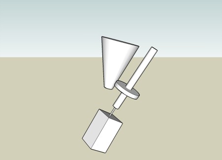
I've never done something like this before, but here's my angle on it. Connect a cone-shaped gear to the output shaft and have the pinion gear (the one attached to the motor) move up and down the length of the cone to change the ratios. Ideally the width of the pinion would be the same as the mid point of the cone. This way the 1:1 ratio is in the center and then it can move either way for more torque or speed.
The diagram is a little rough since I'm not very skilled with drafting programs. The box is the motor and the shaft coming out fits inside the shaft which has the pinion gear. The shafts should be able to "slip" so the gear can move up and down the length -- this allows it to move up and down the gear while still being driven by the motor. A simple approach would be to use square shafts.
Somewhere a servo will be needed to move the pinion up and down the cone gear. This could be done by attaching a regular bearing to the shaft and having the servo attached to the outside of it.
To get more advanced we could add a wheel watcher (http://www.solarbotics.com/products/gmww02/) to automatically monitor the rotation and speed of the wheel and adjust the ratio accordingly. At that point it would become a fully automatic transmission and the microcontroller would just tell the setup how fast we want it to go.
So overall this is a pretty big project. Anybody have thoughts or other implementation ideas? Where do you think I could aquire the gears and slip shafts?