


48-wheeled Rover 5 - Mechanum Wheel Test
Introduction
This Rover 5 platform was received with damaged wheels so I decided I'd give mechanum wheels a try. Unfortunately the cheapest set of mechanum wheels I could find was outwith my limited budget. I turned to Thingiverse and found this relatively simple design (other designs are available but use bearings or other special parts). It took me a few visits to MAKLab, making use of their Ultimaker 3d printer, to print all the parts for the wheels.
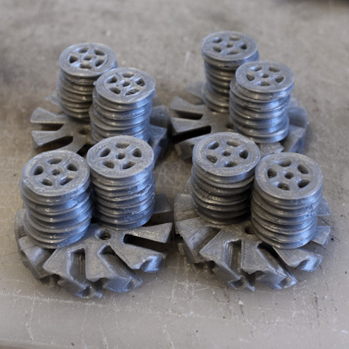
Mechanum wheels printed on an Ultimaker from a Thingiverse model.
I ordered the O-Rings from Farnell (as recommended by the designer on the mechanum wheel thingiverse page) and set about sanding down all the parts. It took me a few evenings to complete all four mechanum wheels. Time was spent sanding down the individual wheels and hubs, drilling out the wheels to run smoothly on the filament. Gluing the wheels to the hubs was rather delicate and on more than one occassion superglue wicked its way into the wheel and I had to start again with a fresh wheel. Several of the wheels are a little stiff and I'm sure that this will have an adverse effect on the operation of the mechanum wheels but I decided to forge ahead and mount them on the Rover 5 base.
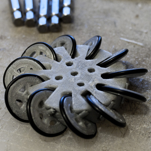
20/01/13 First completed wheel. O-rings provide the running surface and some waste filament used as the axles.
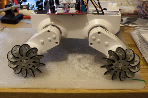
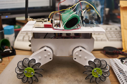
23/01/13 Installed (hot glue for the win!) and waiting for test sketch.
Electronics
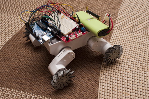
I ordered a replacement (see magic blue smoke) Dagu 4 Channel Motor Controller from robosavvy and soldered the motor leads to it (I didn't have any suitable wire to extend the leads and I also lack the motor connectors, though they are available from Digikey). For testing I setup an Arduino UNO and an APC220 wireless serial module. I'll likely upgrade to an Arduino MEGA in order to have more interrupt I/O pins to handle the quadrature encoders. As this will just be a RC robot for testing I shouldn't need the feedback.
Software
Code for the remote control of the robot is quite primitive. Serial data is sent by the remote controller when the inputs change (i.e. when a stick is moved). I haven't made use of the analog stick on the remote yet, though it's values are being transmitted. A potentiometer on the remote controller is used to set the PWM speed. The other stick is digital, closing a circuit when the stick is left/right/up/down and can report 9 positions (Up&left, Up, Up&right, Left, Centre, Right, Down&left, Down, Down&right). Instead of parsing the data into command strings in the remote controller I've simply relayed each of the switch states as a single byte in the least significant nibble of a byte (the most significant nibble is used as an identifier to differentiate between ASCII text, left stick digital data or analog data (right stick & speed dial)). With this arrangement I'm leaving it up to individual robots to use this however it sees fit. This Rover 5 robot will drive in the direction of the left digital stick while the right analog stick will spin the robot and the speed of movement is set by the speed dial. A future tracked robot could use the analog stick to set forward/reverse and spinning speed based on just the analog stick's position, leaving the left stick for control of accessories (i.e. a gun turret).
Results of the Mechanum Wheel First Test
Between the quality of print that the Ultimaker currently produces (slack on one or two of the belts means the small wheels aren't perfectly round) and my clean-up process with a hobby knife, sandpaper and a few drill bits I'm not sure this test is a true representation of what this design is fully capable of. That said, I'm pleased with the resulting movement on carpet. Implementing feedback from quadrature encoders to ensure that each wheel is turning at the correct speed may help and further feedback from a gyro/compass to detect and correct for errant rotation might overcome the shortcomings in quality of these mechanum wheels.
Remote Controller
Between 23rd and 26th I jumped over to a parallel project, building a remote control for this robot (and possibly for use with others?). I had all the parts: an old radio controller (was for a tank), pair of APC220 wireless serial modules, a freshly bought Arduino Mini and an LCD. I sketched out what I wanted and threw caution to the wind and started soldering it together (normally I'd breadboard test it all but I didn't want to put pins on the Mini). I had a few small hurdles (mostly due to my haste) but when I got a wireless serial link with my PC (could see stick positions and could remotely set the LCD text) I was overjoyed. I still have one hurdle to leap, closing the case (I need an extra 10mm from somewhere)...
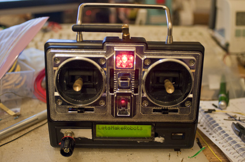
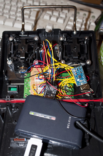
Inside of controller, shown with USB connection for programming the Arduino Mini.
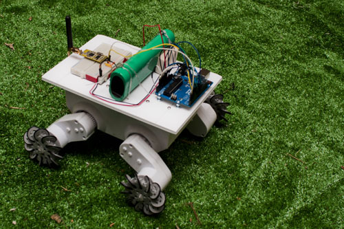
Tidy up
I thought the robot was a bit messy. With everything loose I didn't have high hopes for transporting it to show it off. While in an art store I spotted this foam-core and it struck me that this was all I needed to secure the components and tidy the robot up. This is the first time I've used foam-core and it's a great prototyping material. I had a platform upon which rests the arduino, battery and APC220 (wireless serial module) in an hour or two. Hanging underneath is the motor controller with holes through which wires/jumpers can access the board.
I took the 48-wheeled Rover 5 along to MAKLab (which, if you recall, is where I printed the wheels) to show him off but discovered after driving it for a while that three small wheels on one hub were missing (later found in the boot (trunk) of my car). The lack of three little wheels didn't stop him performing for everyone even with a slight limp. The wheels are now glued back in place and I'll know not to put the robot too close to fixtures in the boot of the car (especially with the speed bumps and potholes I have to negotiate).
Hubcaps
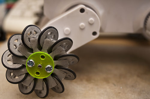
I had the wheels held on with hot-melt glue, which worked fine on three of the wheels but on the fourth it had lost it's ability to grip the shaft. Rather than lathering on more glue I figured it was time to do something to more permanently hold the wheels in place and transfer the torque from the shaft to the wheel. I drew up the part after taking dimensions from the wheel and the shaft. I picked out some scrap perspex in a nice glowy green-yellow (fondly reminds me of some of the LEGO pieces which came with the M-Tron set I had as a kid) and cut a disc. The dimensions of the holes were spot on but there was too much room for the shaft and I wanted a tight interference fit. I scaled down the shaft-hole by 96% & 94% to get two different grips. A disc with a larger hole goes onto the shaft first, it is a nice fit and provides a little resistance to axial movement, followed by the wheel and finished off with a disc with the 94% scaled hole which is a struggle to get on and off the shaft. Two M4 screws (originally 25mm long but cut short to suit) hold everything together but more importantly transfer the torque from the discs to the wheel.
I've been carting the robot around in a plastic bag and it is taking it's tole on the foamcore as you can see in the photo above. With this brief foray into laser cutting perspex I think the next step might be a replacement for the foamcore together with some asthetic touches.
Drives sideways
- Actuators / output devices: Rover 5 base, 4 geared motors with quadrature encoders
- Control method: radio control
- CPU: arduino uno, Arduino Mini
- Power source: 7.2V 3800mAh Ni-Mh
- Programming language: Arduino
- Sensors / input devices: none yet
- Target environment: indoor