


#2 - unbalanced
ABSTRACT: My intention with this paper is to document the robots progress so far and to create list of thing which have to be done to see it finished. I will do this by first creating a overview of the parts in use. Secondly I'll provide some information on how I plan to proceed.
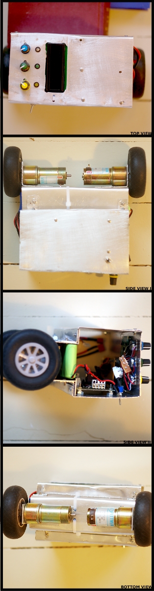
- MICRO CONTROLLER: I'm using 2x ATmega328P. One is used to control three feedback-LED's and the LCD, while the other ATmega is used to control the motor's, wheel encoders and get feedback from sensors. The latter can be looked at as the master, while the second is the slave. In my previous robot I used the Arduino board, but in my quest for greater knowledge about the robot-god I removed this abstraction level. This free's me from using the Arduino Java-based IDE which I fast grew tired of, but forces me to digg deep down in AVR-datasheets. Some would say this was a bad trade-off.
- MOTOR DRIVER: I have built this PCB on my own. It is my first real PCB and I'm rather proud. I've managed to blow it up 3 times I think. Probably something to do with short circuits etc. But last time I checked it was working fine. It's based on a L298N, together with a tri-state switch. It also serves as the volt-regulator for my project, providing me with +5V off a LM2940CT.
- FEEDBACK: I will use three LED's seen on top as Feedback - and an LCD Display. I'm not sure if I'll use a graphic LCD or a 2x16 LCD, yet. I also have installed three colored knobs(potentiometers) for live debugging and configuration.
- SENSORS: Using one accelerometer(ADXL203CE +/-1.5) and a Gyroscope(ADXRS614 - 50°/s). Both chips are from Analog Devices attached to Sparkfun breakout boards. I'll probably add some more info here on a later stage. 1
- WHEELS: Biggest wheels for R/C airplanes they had at the local Hobby store. I like them.
- MOTOR & ENCODERS: I will use two DC gearhead motors from Pittman(ModNr.GM8712).
Their spec's say 19.1V, but my plan is to run them on ~22V. They have a 60.5:1 reduction gearbox, with a stall current at ~1.7A. I'll create some wheel encoders based on the QRD1114 reflective object sensor roughly based on this design. - BATTERIES: two 11.1V Lipo's connected in series for motor and a 2300 m:Ah 6.0V Ni-Mh pack for logic.
- MISC: I will play with a 12-bit A/D Converter(MCP3208) and see if I'm able to use that instead of the built in ADC on the Atmel chip. I will run the ATmega328P at a higher clock count then the arduino to increase the instructions per second (IPS).
- MATERIALS: In my previous design I used Plexiglas. This is changed out for Aluminium sheets with different thickness'. Alu is easier to work with as it is less fragile and it's possible to bend it if needed. Cutting it can prove difficult at times unless you are in possession of some machine tools. I've used a normal Hacksaw, but a band saw would probably be prefferable.
- For motors I need to add filter capacitors and finish my encoders. Encoders are currently in the testing stage - trying to figure out the best way to gather info.
- Sensors need lots of testing. Goal is to get the most precise result. Special care must be taken to volt reference and temperature measurement. Sensors are already mounted at the level of wheels - to avoid measuring falling acceleration.
- Everything except for pots and leds are not cabled up. Neither have i added the second Atmel chip yet. So lots of work to do here.
THEORY OF BALANCE: The theory of balance is both simple and advanced. The idea is that we get some input from a sensor, we then run the input through a formula which calculates the tilt. Based on amount of tilt we send a amount of volt to the motors.
Knowing the angle of the robot lets us calculate torque applied by gravity using the following formula; mass * length * gravity * sin(degree) = Torque in Newton meters. Knowing this gives an indication of what kind of torque we need to counter the falling robot. So torque applied [Force at wheels * length * cos(degrees)] has to be bigger than the torque applied by gravity to overcome it [mass * gravity * length * sin(degrees)].
That was the simple part. What makes this process of balancing all hard and time consuming is the problem with reality and our model in general. Getting an exact point of balance using one sensor might not be as easy as first thought, and therefor there is no simple way of knowing the tilt. Combining several sensors to get exact readings of the robots position relative to earth is essential. This adds more theory or mathematics to the project through the use of filters. Filters combine two or more sensors, remove spikes caused by electronic noise, and as a result you'll get an estimate on a angle. The correctness of the estimate is on one side affected by the hardware in use – and on the other of the filter. One common and relatively advanced way of doing this is by the use of the Kalman filter. Already used on the in the 1960's on the Apollo, the Kalman filter has proven to be good both for space shuttles and balancing robots. You could also combine a couple sensors and calculate the average and call it a filter. This would probably be better then just relaying on one input, but not as good as more advanced options. As a final result is the stability of your platform.
MISC: I would also like to point out a warm "thank you" to all the commenter's in my previous post. Most of the suggestions to increase stability and such are on my todo list for this robot.
RESOURCES:
Theory
- Kalman Filter Made Easy
- What is PID stuff, anyhow?
- Kalman filtering of IMU data
- Jordi Muñoz Kalman implementation in Arduino C
- The Kalman Filter
- Another document on balance filter
- Kalman filter for idiots
Similar projects
- myDanceBot
- How a Kiwi Built an Interactive Vision Guided Robot
- nBot
- Balancing Robot Project - "Bender"
- Segwii
- Daniel Bauen Balance bot
- GyroBot
- Links to other self-balancing-projects
- Analog Balancing Bot
- Equibot
- JOE le pendule's bot
- Balancing Robot
- Segwii
- b3r1 - Google Code
- bla repository » Archive » Inverted pendulum, balancing robot
- generation5 - Legway: Building a Self-Balancing Robot with Standard Parts
- http://www.geology.smu.edu/~dpa-www/robo/nbot/bal2.txt
Balance
- Control method: autonomous
- CPU: ATmega328P
- Operating system: Linux
- Power source: 22.2V Lipo, 2300 m:Ah 6.0V Ni-Mh
- Programming language: C
- Sensors / input devices: ADXL203CE, ADXRS614 - 50°/s
- Target environment: indoor, outdoor