


16 Transistor Homebrew Minimalistic Naughts and Crosses (Tic Tac Toe) Robot
This robot was created as an entry for Oddbot's challenge: https://www.robotshop.com/letsmakerobots/node/35296
I learned a lot with this project: just check out the Reflection below!
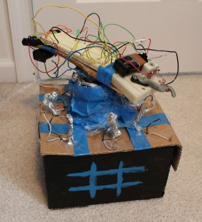
Here is how this guy works: a drill motor spins around and the LED on the breadboard displays whether the sensor is high (meaning the robot moves there) or low (led off). The servo is for good looks: connect a wire to ground and it will open up, and this stops the drill motor from moving. I planned to incorporate it via h-bridge to point at the spot it would move to, but I decided to keep it at a minimalistic level of logic (only 16 transistors... they are not needed but can be used. Again, check out my reflection part for a full explanation on this). The servo is now my on/off switch for the spinning!
Due to the position of the drill, the robot always moves first into the center square. After the user goes, the robot will then respond (via the led). The robot surprisingly works, and will win or tie every time! If you don't think that it spins, the third video is proof!
-------------------------------------------------------------------------------------------------------------------------------------------------------------------------------
Reflection:
This is perhaps the project that I have learned the most from! My first tic tac toe idea was to build a 16 transistor board and have it display on another breadboard with 2 led lights per square- one for the robot, and one for the user. However, Oddbot said that his goal was a moving robot that played tic tac toe. I tried to interface the 16 transistor board with the robot, but it would just not work right with my first setup. To make matters worse, the internal 9v would not supply enough power to my servo, as I had to add a resistor to keep the internal transistors from burning up. Right before I started to make a movie I had an idea: since the goal of my transistor board was to have the robot move to the square next to where the user went, I connected each of the sensor's wires over to the next square. Whenever I would plug in the black wire (ground) to the sensor the led would light up. This setup would result in a win/tie every time, so I decided to record it this way. My minimalistic approach from the transistors just became a whole lot more minimal: only sensors and one motor.
The last two images are of my transistors inside of the robot. After I recorded the first three videos I fixed the interface issue and had it transistor controlled... but the only difference is that I plug the black wire to ground (a hole next to/behind the sensor) to turn on the sensor next to it and not to the sensor itself. This is shown in the last video. The end result is the same: the robot moves into the square next to the user. At least this proves that my original interface design was totally viable (although not needed). The only "issue" is that if the user goes in two squares next to each other the robot does not know how to respond... although if you were to do that you would technically loose (so it is not a problem for "normal" games).
By May I plan to have 4 more robots posted: 2 maze robots and 2 sumo robots: all of which will run on the arduino. This project was a great opportunity to take a step back and become not so dependent upon my collection of arduinos and other micro controllers, as well as to learn a thing or two about transistors (and how they are not always needed). Thanks Oddbot! I hope you see my robot's mess of wires, tinfoil, bad paint job, ect. creativity!
-------------------------------------------------------------------------------------------------------------------------------------------------------------------------------
Plays Naughts and Crosses (Tic Tac Toe)
- Actuators / output devices: Drill Motor/Scavenged Servo
- Control method: 16 Transistors (not needed)
- CPU: none
- Operating system: N/A
- Power source: X4 AA batteries and X2 9v
- Programming language: none
- Sensors / input devices: Tin Foil =)
- Target environment: indoors