

Rout-X, my CNC router

Long time ago, about 5 years I think, I started looking up DIY CNC machines. I bought the 4 axis EZ Driver combo kit from Hobby CNC, together with the CNC plan they had at the time. But I didn't had time to order the acme screws and linear bearings and I left USA and returned to Romania. Over there, I had an attempt after this site, but it didn't came out good as I did some mistakes. I had to abandon it when I came to Canada, but took the electronics and motors with me. Here I almost bought (something happened and ran out of money) a ready made machine with no electronics or motors for $300 from the guy that makes the Rockcliffe boards. Now, after so many years, I decided to make my own machine instead of buying a kit. Although this kit did not seem expensive, considering that I put almost $200 in parts and lots of work to build it. But I wanted a bit more Z axis travel, so I can add an extruder and make 3D parts.
Yesterday I finally got the bearings from a local skateboards and roller blades shop (Cardinal Skate). It was a hard task to find cheap bearings in Toronto, but after 3 days of Google-ing the internet and driving around city to find closed down stores or no bearings in stock, a few (huge) quotes from bearings distributors, I tried Yahoo by mistake and found the Cardinal Skate store. I got 40 bearings for a little over 80 dollars (CAD) including taxes. If I would have decided to buy V-groove bearings from VXB.com at $7.70 a piece, I would have paid $123.2 plus shipping (and eventual taxes) for 16 pcs. That would have made the track construction much easier... Oh well...
I got a 2'x4' 3/4" MDF board at Home Depot and I had it cut in several 24" long pieces: one piece 17" wide for the table, 3 pieces 6" wide for the sides, 2 pieces 4" wide for the Y and Z axes and 2 pieces 2" wide for... I don't remember what they were for.
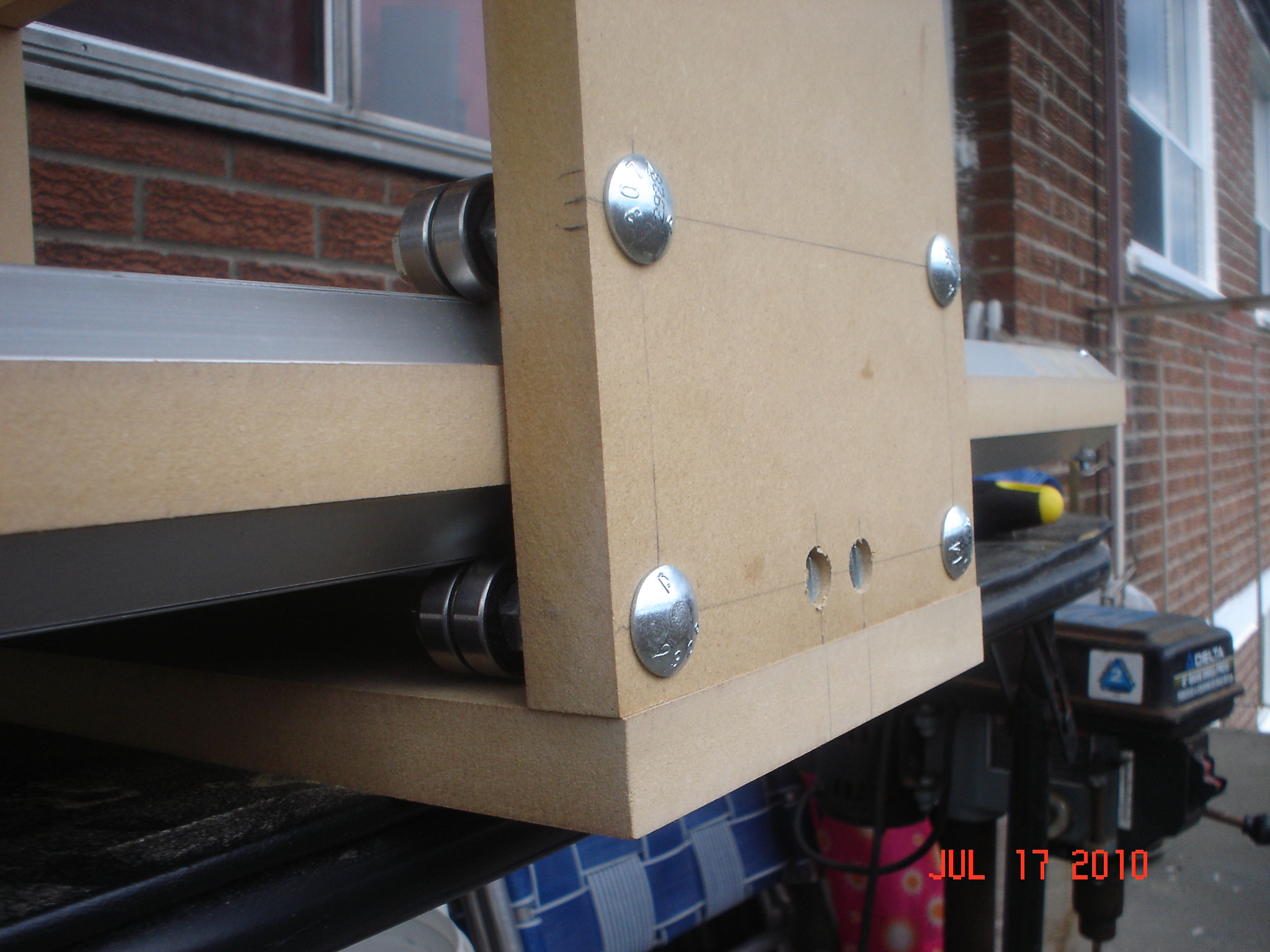
So I got pretty much everything I need, except the routing bit. Why I need that? Because I decided to make a hybrid between the CNC from the videos on the BuildYourCNC.com and TinHead's Valkyrie. I will use double bearings with a washer in between that will ride on the outer corner of the aluminum L profile. I the videos, the guy uses a router to chamfer the boards to mount the aluminum angles. I don't have that tool, but it crossed my mind I do have sort of a router, a Dremel. All I needed was a chamfer router bit for Dremel. I Google it and found it. But hey, I live in Canada, not the States. Here, you can find in the stores the Router attachment for the Dremel, but no router bits. How do I do it then? I just bought a #10 quick change countersink drill bit, pulled the bit backwards until it came out about 5 mm from the countersink (front) part, mount it on the Dremel and mounted the Multipurpose Cutting Guide attachment (http://www.dremel.com/en-us/Pop-ups/Pages/ProductImages.aspx?pid=565&tab=1). This setup worked so-so, as the bit is too long and vibrates a lot, but I could chamfer the boards a little so I can mount the aluminum angle.
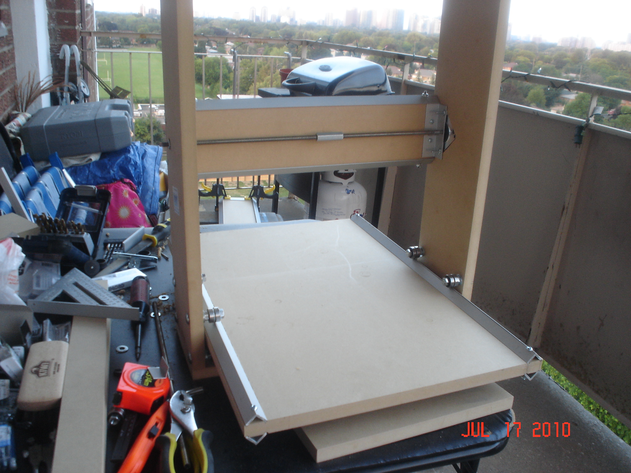
Then I decided I should start from the table, and see if I can route channels for the aluminum angles to rest directly on the table instead of the 2" pieces (ah, that's what they were for!). I clamped the angle as a straight edge and used the Dremel again with a end mill bit. That worked pretty good, so I had the angles installed and bolted at the ends to the table. Then I drilled and mounted the bearings on one side at the end of the board and hanged the side on the board upside down, with the bearings on the track. using another bearing assembly (bolt, washers, nut, bearings) on the side of the board and marked the position for the second row of bearings, then I drilled and installed the second row and mounted it back on the track. I rolled a bit tight, but I can adjust it later or it will give in at work. One side done, on to the next one. I followed the same steps and in the evening I had both sides mounted on the tracks. I turned the table upside down and traced and cut the bottom plate and mounted it on the sides using cross dowels. I will install 2 more screws after I'm done with mounting-dismounting the sides for different operations. So, the X axis is done, except the motor mount and lead screw.
Jul. 17, 2010.
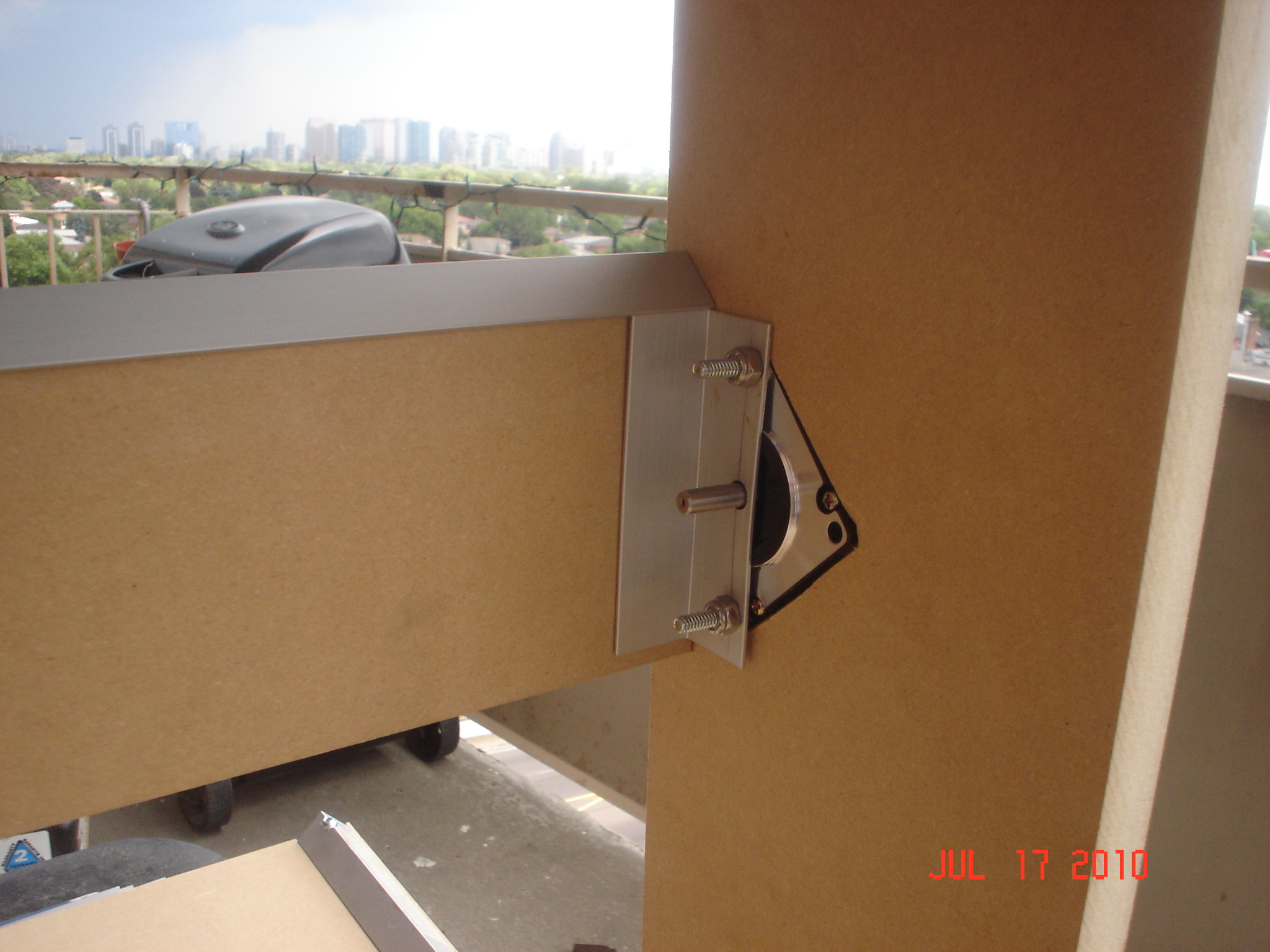
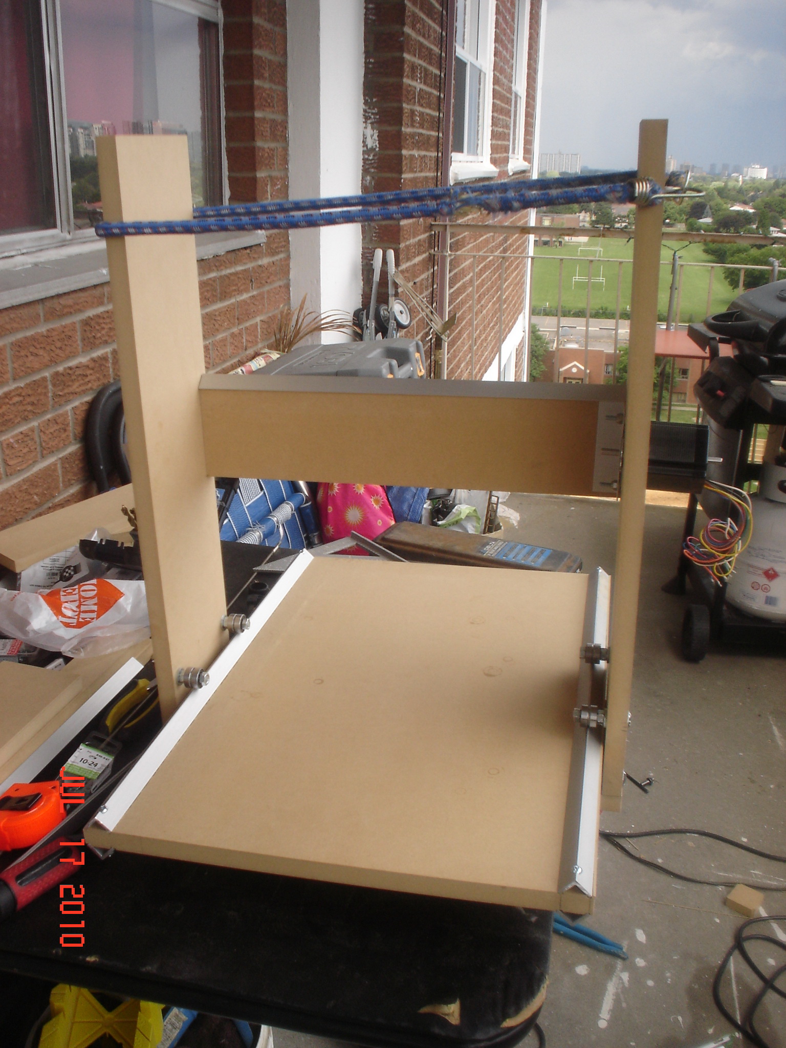
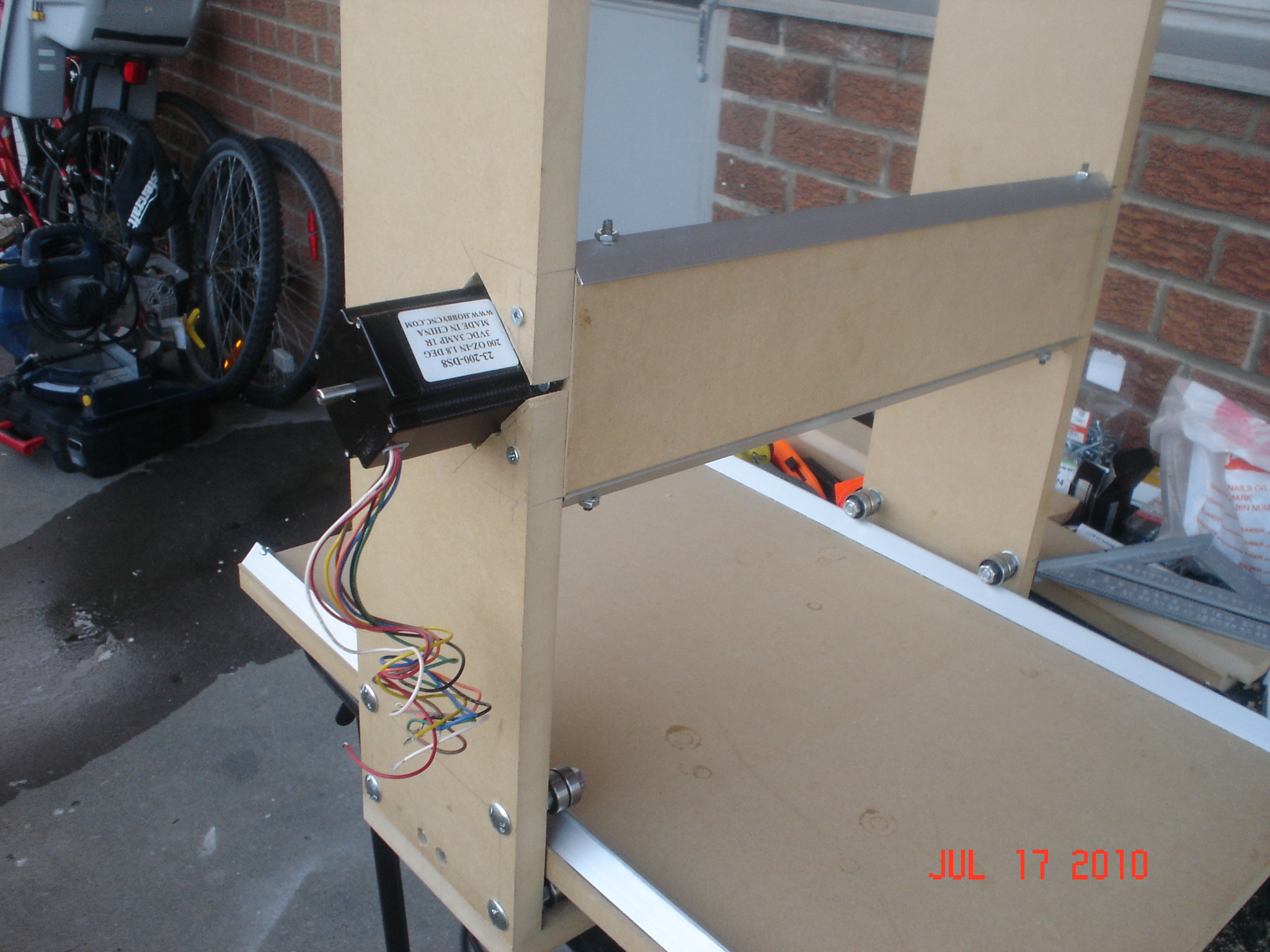
Today I put the assembly on the "work bench" and figured the placement height for the Y axis board. I cut a piece of 1" aluminum angle, 3 1/2" long, and drilled it to make a motor mount. The motor will be mounted at 45 degrees and it will be protruding though the router side, so I traced it, drilled the corners and cut it using a Jigsaw. I left the sides 24" long at the moment, I will cut them to a proper length later. Now I need to mount the tracks on the Y axis board and drill the hole for the bearing that supports the lead screw. Then I'll make the Y axis slide.
A few pictures:
That's it for now, I had to make a break so my kid can take an afternoon nap. More to follow in the evening.
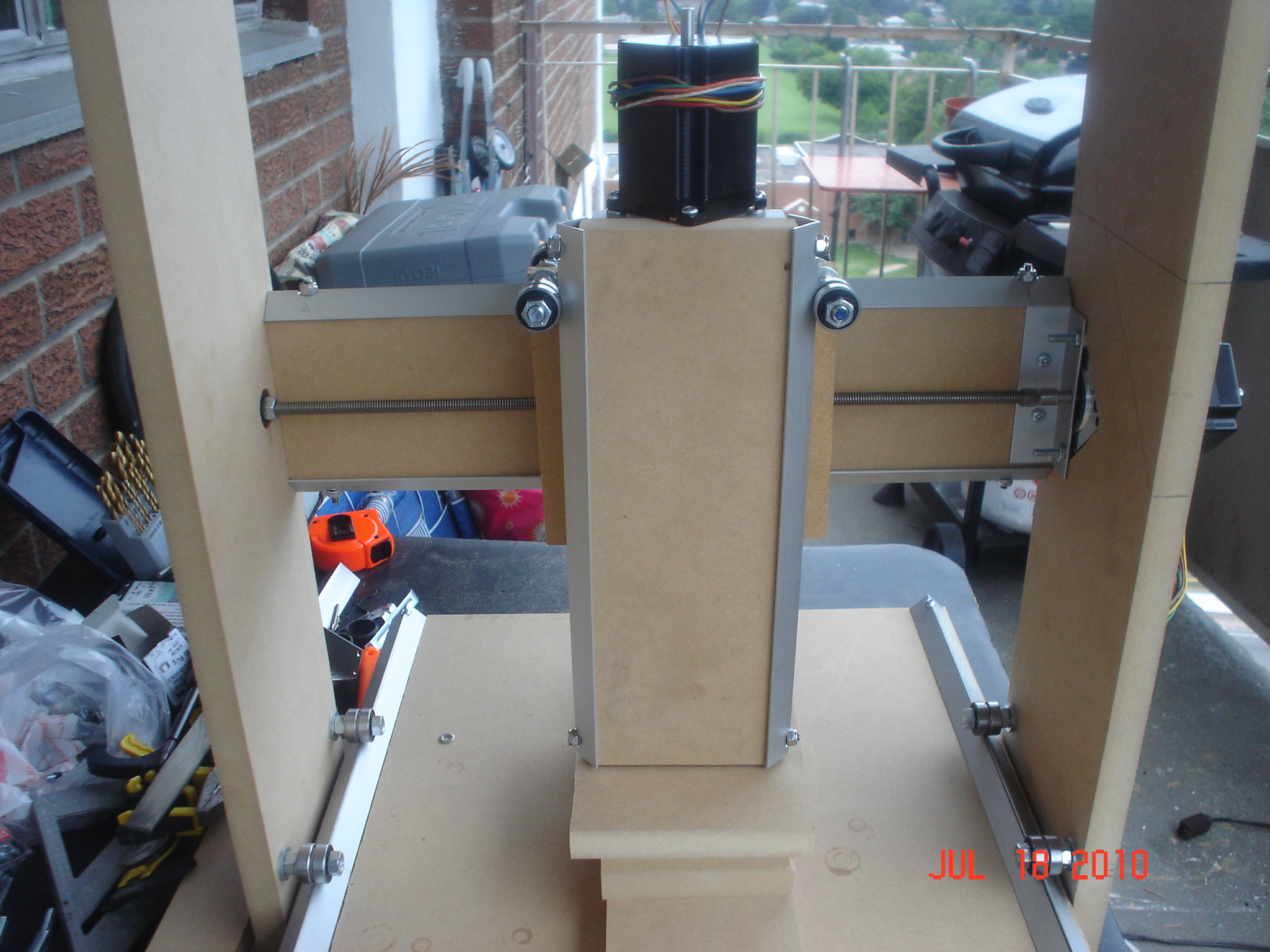
After the break I managed to make the Y axis complete with the motor mount and lead screw. I used a 10-24 threaded rod that I cut into pieces to mount the aluminum angle to the board and a piece of 1" aluminum angle to mount the stepper motor. As I said, the motor is mounted at 45 degrees, 2 bolts to the aluminum angle and one screw to the Y axis board. The lead screw is supported at the end by a ball bearing. I used a drill to turn the screw to see how it moves the nut and I found that the screw is not centered in the bearing, so I will use some electrical tape to center it. I clamped together the angles for the Z axis and hanged them on the motor mount on top of a lead screw placed vertically to see how far out the Z axis will end up. The Dremel will be a little before the line between the front bearings on the X axis, which is not optimal, but it's my first build and I did it without CAD-ing it first and no blue prints. Just a fuzzy sketch in my mind. But I think it will work good enough, as I don't expect a high quality machine.
Here are some more pictures:

Oh well, tomorrow is another day...
Jul. 18, 2010.
Today I started by cleaning a computer I found in the garbage at my building. One of the benefits of living in Canada or the States is that you can find stuff like this in the garbage or on the side of the road in the subdivisions. The computer is a Pentium 4 at 2 GHz, with 512 MB RAM and 40 GB HDD. And the best part: it has a 15" DELL LCD! Unbelievable! I am so lucky! After the cleaning I erased the partition and installed XP on it, then downloaded the Ubuntu with EMC2 and installed it over instead of dual boot with XP. I can install Wine, but anyway, I will use my laptop to draw the parts and transfer them through my network on the Linux computer to send them to the CNC. Perhaps I'll learn some more Linux this way...
On the machine I built the Z axis completely and started to work on the double sled, but guess what, the 1/2" board I had was too small so I couldn't finish. Tomorrow I'll get a bigger board and make the sled properly. Last part will be the X axis motor and lead screw mount.
Here are today's pictures:

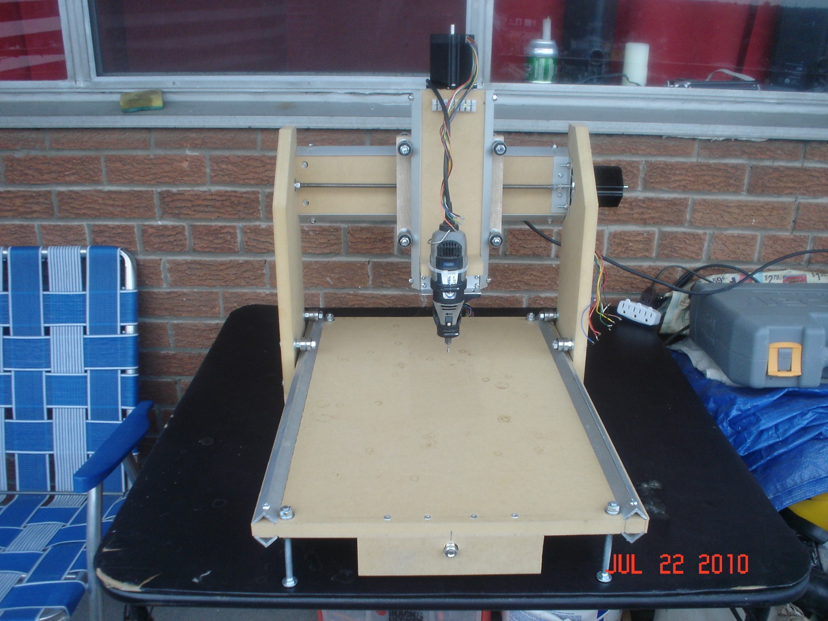
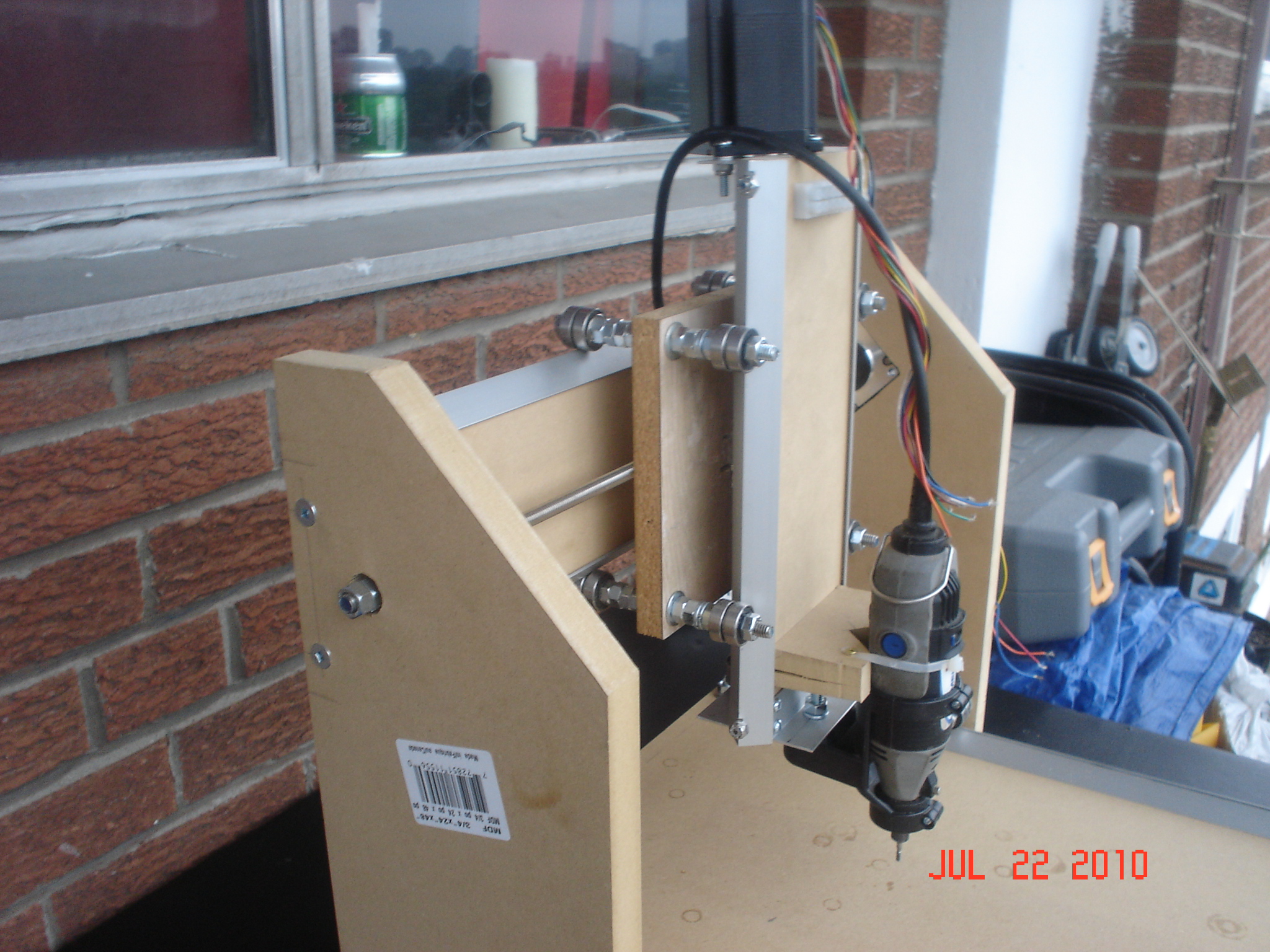
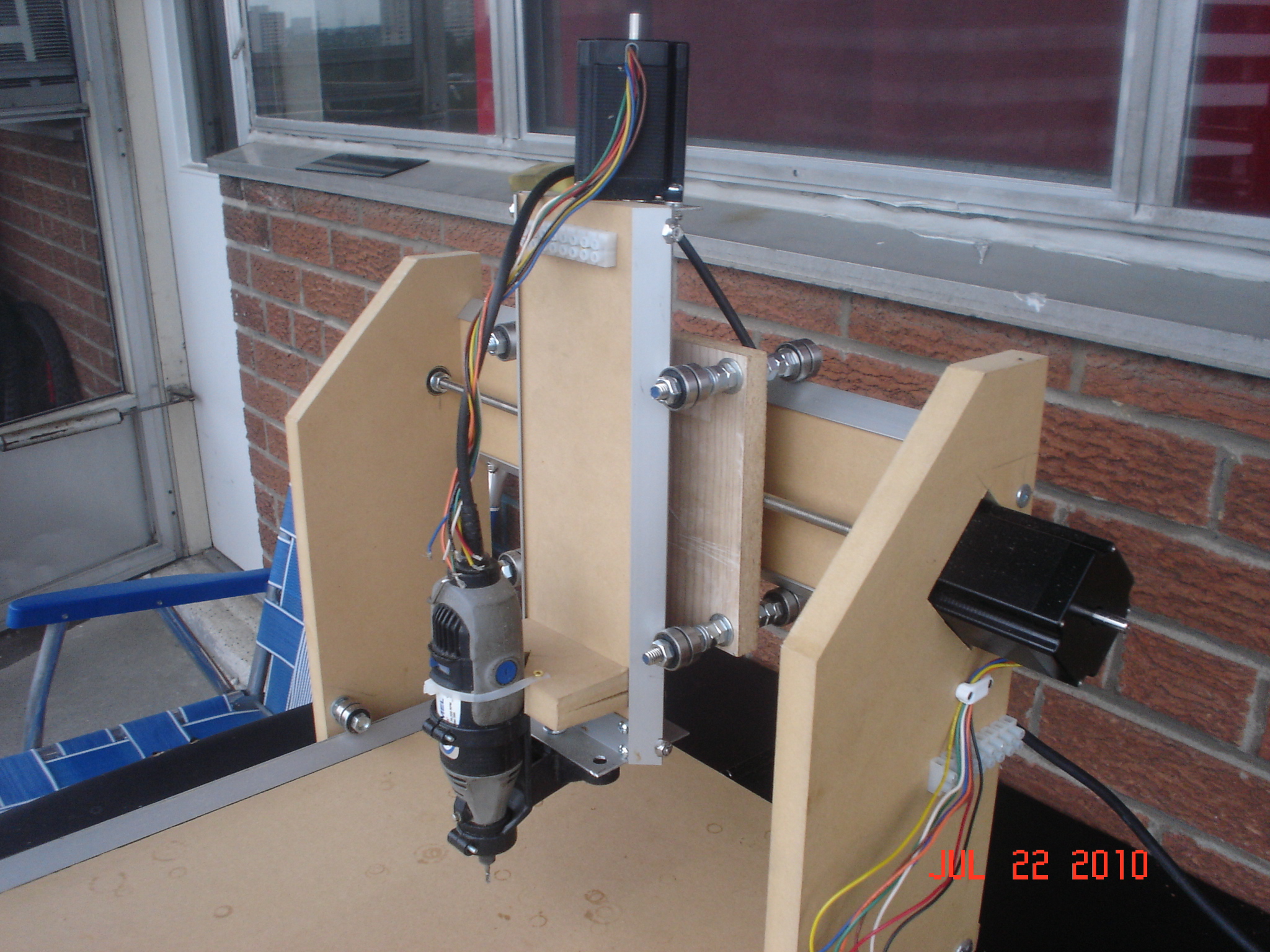
Jul. 22, 2010.
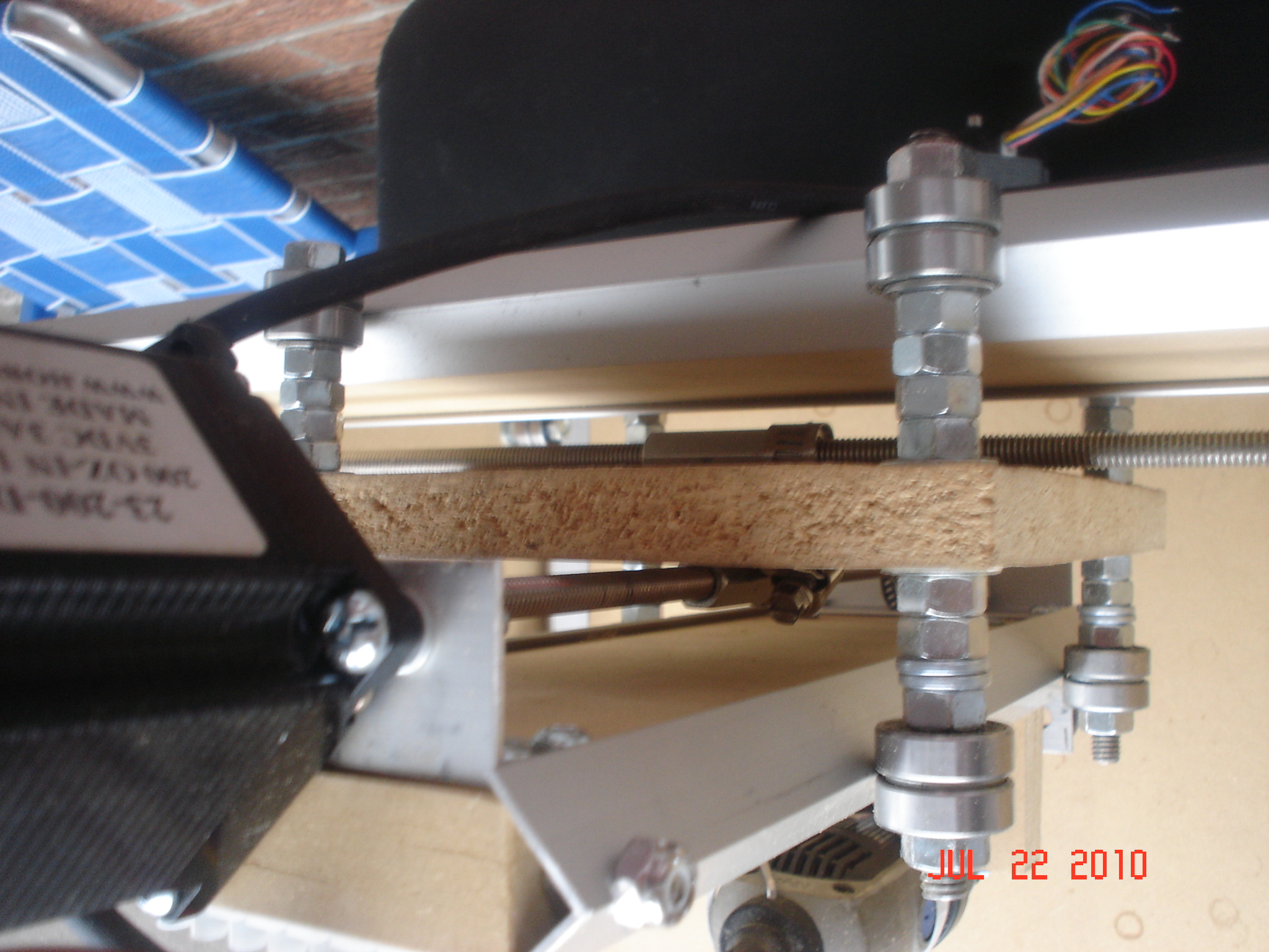
After 3 days of work (I was supposed to be in vacation... stupid emergencies...) I was able today to finish up the mechanical part of my CNC. I have to say that lining up the lead screws was the hardest part. I had to take them apart a few times to get them right. The Y axis is still a bit tight, but it'll have to work for now. Next machine will be easier, as I can make the cuts with this one and I'll just have to assemble it. That is if I wont make any mistakes while CAD-ing. The following pictures shows the machine front, the double sled assembly, where you can barely see the drive nuts mounted like a cross, one on each side of the board, held in place by screw clamps and stop screws so the nuts don't slide if the clamp became loose. At the moment I'm using the Drill attachment for the Dremel as a tool mount but I plan to cut proper ones with the CNC. I have to measure the max travel distance, as I think it is smaller then I planed. Not a big problem, but I have to set up EMC2 anyway.

Tomorrow I'll make the electrical connections and hopefully I'll make the first tests.
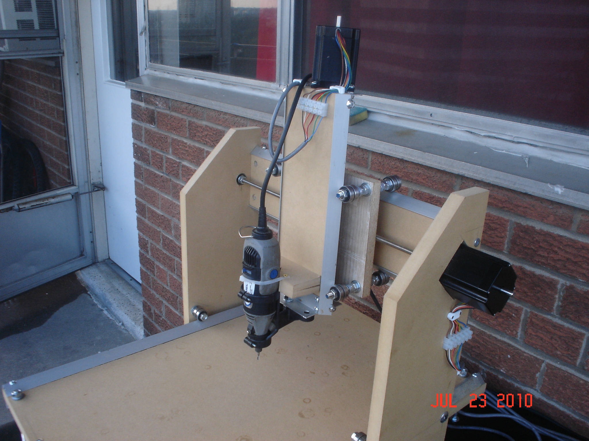
Jul.23, 2010.
Today I managed to mount both the driver board and the ATX power source in the same plastic project box. I mounted a Power ON switch (that connects the green "Power Good" wire to ground) and a LED through a 330 ohm resistor to 5V. I braided and twisted 3 yellow wires (+12V) and 3 black wires (ground) and connected them to the driver power connector. All other wires from the power board I cut and isolated using electrical tape. I have one fan in the back of the box (connected where the power source fan used to be) and I will add a second (bigger) fan on top of the box, or a similar fan in the back. Depends how hot the radiators will be. This part took a bit more than half day.
Connecting the cables to the motors was easy, but also took more time than I thought. But I got it done and checking with the multimeter reveals good connections. But I am too tired to set up the software and try to jog the axes and see how they are working. Oh well, tomorrow is another day...
Here are pictures of the box and wiring:

Jul. 25, 2010.
YES!!! It works!!! I was an idiot 3 years ago when I assembled the EZ Driver! I accidentally swapped 2 resistors in the Vref circuit, so I was getting 4.84V instead of 0.84V at Vref test point. I thought I damaged the ICs, but happily, when they get over 2V at Vref pin, they are in release mode, so the motors are free to run (or move by hand). I figured it out by looking at the datasheet (hehe, RTFM, I know...) and checking the values of the resistors with the DMM. When something seemed fishy, I looked at the assembly instructions and I realized the mistake. They were not easy to swap back, but I did it, and, while I was at it, I re-flowed all pins.
So today I will take it back outside and I will cut something... complicated. I don't have patience to do something easy first, then step it up. I'l just try a MDF 3D carving. I tested the file "in air" and it works, now I have to start cutting. I'll take a short video near the end of the cutting, cause it will take a few hours for it to finish. Wish me Good Luck!
Jul. 26, 2010.
After 12 hours of work, the carving was still not ready. I started it around 6 PM yesterday and around 8 I changed the mill bit from a regular conical Dremel bit to a straight end mill, because the conical one was not proper for a cut like this. I also had a problem at one point near the beginning, the motor slipped inside the plastic coupler so the machine lost it's place and the mill came out of the board. Unfortunately, the machine vibrates in different tonalities, it's like somebody is practicing playing horn and my downstairs neighbors knocked at my door to stop the noise at 6 AM. Oops! The machine still had about another hour or so to work, but I had to stop it. Did not had time to take a video, for obvious reasons, but I took a picture of the screen and a picture of the board as it was mounted on the machine.
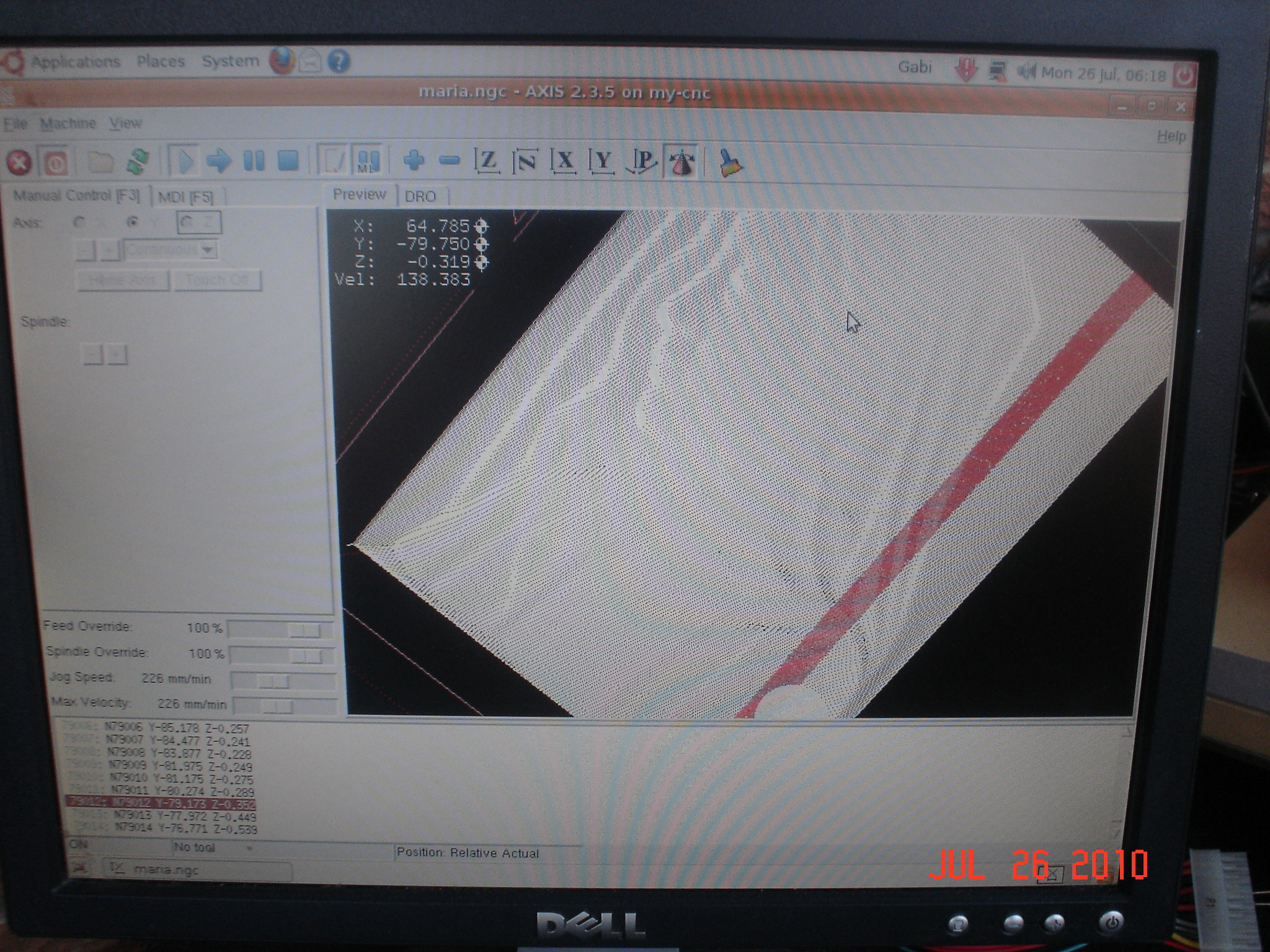
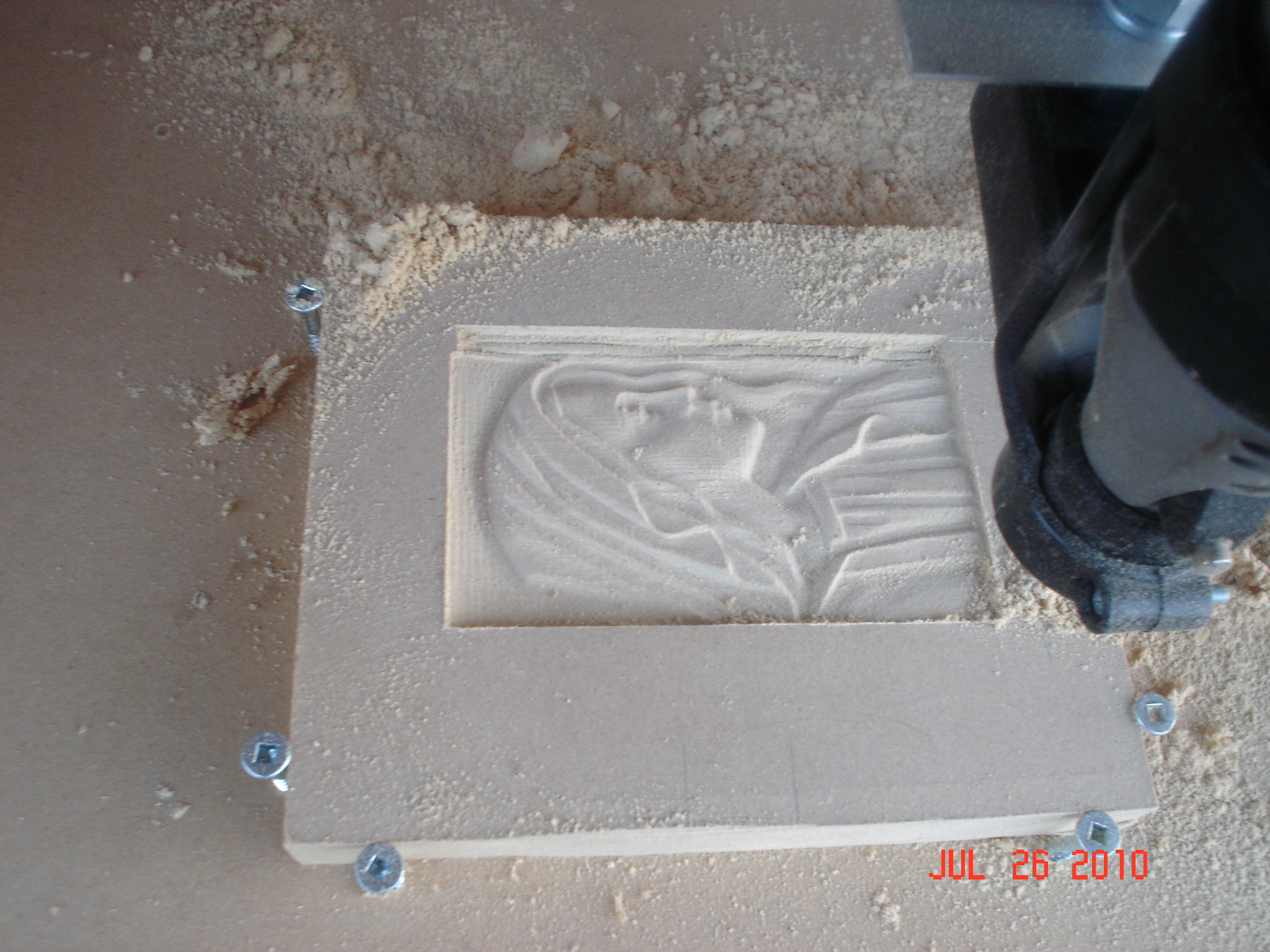
Looks like I will have to invert the X axis, as the picture is mirrored. I got the gcode file from here, changed the extension and opened it in EMC2 and this is the result!
I'm working today, pretty far away, that means I'll be home very late tonight, but I'll try to CAD some writing to engrave and have that one on video.
Aug. 2, 2010.
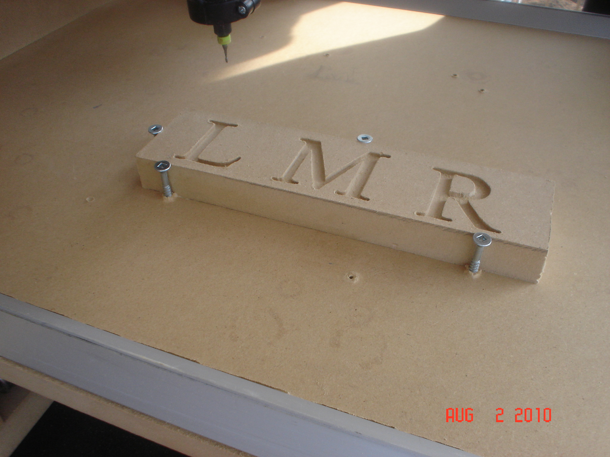
I finally managed to use CamBam to write a text that I could carve out on a piece of MDF. Right now there was no optimization, the edges were burred and I had to clean them after cutting. The depth was set to 3mm, that was a little too much for the 200mm/min speed that I used to cut the text. But the whole process took about 22 minutes. I made a video that I edited using VideoPad, which allowed me to change the speed for a big part of the video and add all related text parts and effects. Enjoy!
Here is the end result picture:
Thanks for helping to keep our community civil!
This post is an advertisement, or vandalism. It is not useful or relevant to the current topic.
You flagged this as spam. Undo flag.Flag Post
Your post is currently under review by our moderation team. The review process usually takes up to 48 business hours.
You can track your post's status in the "My Content" section of your profile. Once approved, it will be published and visible to others.

Thank you for contributing to our community!