imported/stepper-motor-driver.sch
imported/stepper-motor-driver.brd
imported/clone_cnc_reprap_driver.png
imported/clone_cnc_upgrade_motor_wires.png
imported/Proxxon_KT_70_envy.jpg
imported/NextGen_CNC_sketch.png
imported/RepRap_Driver1_2.pdf
imported/RepRap_Driver1_2_0.pdf
In the picture from top-left, clockwise to bottom-left: the terminal block (24V power up to 13A), the 2 X-axis drivers, the Y-axis driver (blue heat sink), and the Z-axis driver (blue heat sink), the Arduino controller (direction x3/enable x3/step x3), and just below the terminal block there is a small 9V regulator board to shift 24V down to 9V for the Arduino. Everything is mounted on an MDF board, and the board is mounted with baling wire.
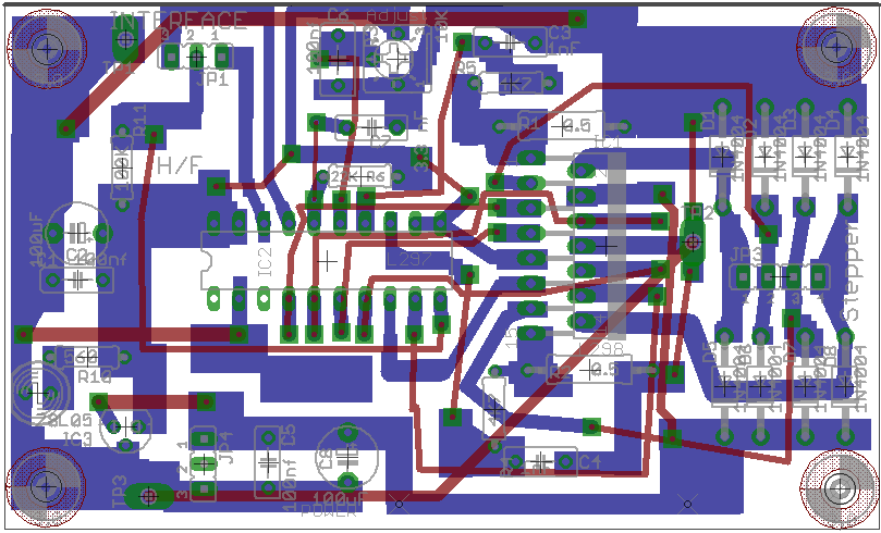
This project is a driver alternative to the Valkyrie stepper driver boards. The RepRap Stepper Driver v1.2 L297/L298 current-limiting stepper driver should let me drive bigger motors on a L298 Driver IC than the printer motors I currently use on my Valkyrie-clone. Most of the RepRap design is right from the data sheet, but there may be some innovations that ought to be credited to the fine folks who built the v1.2 driver (not me!). The "innovation" I added (if it can be called an innovation at all) is that I can fabricate it on my CNC, and it uses connectors from my parts bin.
The reason I'm building this is that I have some motors that require current limiting.
Design Documents
EagleCAD Board file. The design is mostly the RepRap Stepper Driver 1.2 board, except I removed the limit switches and replaced all the connectors with 2.54mm pitch male headers to match what I am using on my "Valkyrie-Clone CNC". Also, the voltage regulation is done on-board instead of via the ATX PSU. If I were starting from scratch I may have wanted to have the Molex connector on-board, but it's cheaper for me to keep my legacy setup and change the board design.
https://community.robotshop.com/uploads/j/o/john-ny/imported/clone_cnc_reprap_driver.png
https://www.robotshop.com/letsmakerobots/files/stepper-motor-driver.brd
https://www.robotshop.com/letsmakerobots/files/stepper-motor-driver.sch
Stepper Driver pricing: https://www.robotshop.com/letsmakerobots/files/RepRap_Driver1_2.pdf
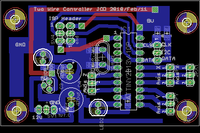
Multiplexer: The multiplexer will take an I2C command from the Arduino and move one of the stepper drivers. Since there are 9x digital channels controlling the steppers, I wanted to move these wires to a dedicated board off the Arduino. A single multiplexer I think may allow a few benefits over the Valkyrie steppers -- The cost decreases by almost $10 by using one ATTINY instead of 4x, stepper driver board size decreases, and the ATTINY becomes easier to program since the ISP header is on-board. Also, you end up with a spare ATTINY programmer (I was using an EvilMadScientistLabs minimalist design initially). The disadvantage is that you have another board to fabricate -- which isn't a problem if you fab your own, but it would be a pain to order an extra board from BatchPCB or similar.
https://community.robotshop.com/uploads/j/o/john-ny/imported/tiny2313_multiplexer_brd.png
https://www.robotshop.com/letsmakerobots/files/tiny2313_multiplexer_sch.png
https://www.robotshop.com/letsmakerobots/files/tiny2313_stepper_0.sch
https://www.robotshop.com/letsmakerobots/files/tiny2313_stepper_1.brd
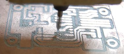
Yes, those are SMD resistors/capacitors, but it isn't too difficult to replace them with through-hole components if needed.
Results
I finished assembling the first driver. Through-hole parts are specified, but I just got my first SMT 1206 (3216 metric) components from an online hobby shop (www.vakits.com) and wanted to try my hand at SMT soldering. So the last resistors and capacitors I soldered were from an SMT resistor and SMT capacitor kit (hand soldered since I don't have a hot plate and the driver was mostly built already). I guess they were soldered okay since the driver works, although I can't tell whether the 10kOhm trimpot makes a difference, so perhaps not everything was soldered correctly. I'll have to post an updated picture of the bottom of the board with my sinfully ugly SMT soldering on display.
The motor driver test was successful at source current of 12VDC. The motors work in forwards and reverse when given 2µsec pulses with a 1000µsec delay between pulses (as measured by the Arduino Duemilanove command "delayMicroseconds()"). A 2µsec pulse will drive the motor one step. I shall be running the motors on 12VDC instead of my previous 24VDC configuration because my ATX supply was never meant to drive large loads on the -12V line (the small steppers I was using needed their full rated voltage of 24V to drive my machine). With these new motors, I shouldn't need to run 24V, and even if I wanted to I'd need a new PSU.
My next step is to replicate my stepper driver boards (I fixed the power supply mistake), and start mounting the motors on the machine.
Update 25/Jan/2010: Fabricated 3 more boards today, and one more is planned for tonight, so I should have all the drivers I need for a 4-axis machine. The CNC works pretty well, except when the board is not flat. Also, after a few hours I need to give it some time to cool down or it may end up working unreliably (like the time it started losing steps in the positive X direction and my drill holes started creeping up the PCB). If I build another machine, it probably won't cost so much -- maybe under $100 additional dollars and a few weekends (ugh! fabrication is hard! I need a CNC router!), and I'll have a second (hopefully smaller) PCB fabricator. Since it takes time to trace a board, I could etch and drill faster with 2 machines than with only the one. But my best use of the CNC has been self-replication (stepper driver boards), so once I finish the second machine I won't want two anymore.
Update 28/Jan/2010: The Clone CNC with its neat printer motors has locked itself up 3 times in a half hour. I realized that I ought to test out my next generation boards with my current generation CNC. I can either move the boards to my computer case, or install the boards on the machine where the old ones are and run some more wires. The issue is that I2C uses 2 wires, but the RepRap boards use 9 or 12 wires to control the steppers (I can run the two X-axis drivers off the same set of control wires. FYI the logic wires are "direction", "enable" and "step" which respectively control the direction of the motor, whether there is a holding current appied (disabling keeps the motors from overheating), and a 2µsec pulse on the "step" wire causes the stepper to step if the "enable" wire is high. I plan to use an I2C distributor to control the 9 channels: I'll modify TinHead's I2C stepper driver ATTINY2313 board to send 9 channels of logic in response to one of several I2C commands. Then I use the Arduino to control the ATTINY2313. This arrangement leaves 13 digital I/O pins free on the Arduino to control limit switches, a "stop" button, and all the other stuff I'm too lazy to implement on this machine. (once I have some hefty NEMA17 motors grunting away I'll need those safety devices to keep my machine from self-destructing but right now it doesn't matter).
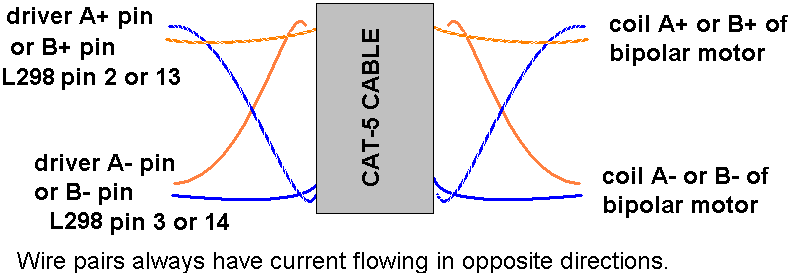
If I mount the new boards in the computer case, i'll need to run some wires to the motors. I'm thinking of using my CAT-5 (or CAT-3 if I don't want to waste quality cable). I want a VS wire paired with a GND wire in the twisted pair, and I want extra copper for the 2Amp/coil motors, so I plan to pair the wires as follows. If I have a blue/blue-white pair and an orange/orange-white pair, I'd run the blue and orange solids to the A+ coil and the blue and orange stripes to the A- coil. When the cable terminates at the motor I'll seperate the solids and stripes and link them to their appropriate motor wire.
If I were instead using only one CAT-5 wire per motor wire, I would pair the A+ and A- wires since for the bipolar motors, the current is always flowing opposite. I think this will reduce EMI caused by the wires.
Update: 29/Jan/2010: Made the first motor cable of four that I'll need. Even though I'm running them for the small Minebea PM42 motors, I still paired up the 24AWG motor wires (as specified in the previous update) for forward compatibility with the current-sucking NEMA17's. I decided that the wires should have a 4-pin interface just like the drivers have, since I've soldered female RS-232 sockets on the wires of all the steppers I have. I made several small interface boards about 30mm x 20mm in size, with the CAT-5e wires soldered in to the board, and connected to some 2.54mm spaced male headers that the steppers should plug into. There are two holes on each board for mounting them on the machine (either with existing holes + nylon bolts or with wood screws). I did the mini-board trace isolation by hand because it'd be quicker to route it manually than with CAD and the CNC. Pics to come.
The Valkyrie-style stepper drivers that run the PM42 motors will be mounted inside the computer case, and I'll have 4 patch cables/CAT-5e cables -- solid core for the X-axis motors (stationary motors), and stranded core for the Y and Z motors (which are on a moving stage). I'm waiting to move to the RepRap 1.2 Drivers because I have an estimated 20 hours of work left to do before I am ready to exchange drivers (creating an I2C distributor board, as specified in a previous update, will take about 12 hours from design to fabrication, and I have only one stepper driver prototype assembled).
Update: 30/Jan/2010: Happy Birthday, LMR! I celebrated with 4 more hours of work to put the driver boards inside the computer case. Pics to follow, but the Valkyrie drivers are mounted in the case, with the motors outside. It's taken 6 hours of work just to take the drivers off the CNC and put them in a case, and run the cables to hook everything up. Tonight I'll dream that I'm still tightening screws and drilling holes and soldering cables...
Update: 11/Feb/2010: I am living in interesting times. I found a "hackerspace" kind of nearby in Fullerton, CA that may be worth investigating (they have a metal/machine shop that would add to my capabilities). I also have a new collaboration with a local fellow who is interested in CNC, foundry work, wood work, and generally cool stuff. In that spirit I'm adding to my capabilities a homemade BoArduino PCB that could serve as a dedicated Arduino controller for a CNC machine. The design can be machined on my Valkyrie-clone CNC on a 4"x2" board (100mmx50mm) -- it's bigger than Boarduino because my tolerances are crap compared to commercial PCB fabrication. The goal is a <$8 BoArduino clone (most of the cost is the $6 Atmel IC). Perhaps it could be part of a 100% DIY self-replicating RepRap-style CNC.
I'm not posting the µC design for now, but anyone can modify the BoArduino EagleCAD files from Adafruit Industries to be a single-sided ATMEGA328/ATMEGA168 BoArduino board. http://www.instructables.com/id/Single-Sided-Really-Bare-Bones-Board-Arduino-in-EA/ or similar designs might be another source of CAD files (direct link: http://homepage.mac.com/westfw/.Public/RBBB-SS-EAGLE-v1.0.zip). The author is an Adafruit Forums contributor, and the BoArduino design shown in the pics is printed on an LPKF PCB prototyping machine.
Update: 12/Feb/2010: I was pricing a duplicate electronics setup for a fellow who was interested in building a CNC using the "buildyourcnc.com" book (http://buildyourcnc.com/Book.aspx). If I have a <$8 Arduino, a ~$5 (and optional) ATTINY2313 multiplexer (node/12713), and these driver boards, I could have a <$60 electronics setup for the bipolar motors (4xmotors for $51 incl. S/H).
Next Gen CNCMy build quality is pretty bad -- I was saved by the elegant simplicity of the Valkyrie design. I built the Valkyrie-clone with insufficient rigidity, so it's not going to be that good at machining materials, and while it's okay for some PCBs, it will not be fabricating for SMT SOIC-8 chips or other fine-pitch components.
Now I'm playing with new motors, new electronics, and considering a new X-Y-Z axis, so it's just a small jump to thinking of building a second CNC. I like having built a whole CNC from wood, blood, sweat, and tears, but the next one I want to be awesome, accurate, and cheap (with less blood, sweat and tears).
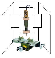
That's why my next CNC may be built with this, the Proxxon KT 70 table ($85 incl. S/H @ Amazon.com). If I use my limited carpentry skills to construct a sound-enclosure and mount a cross-beam across the enclosure, I can mount a static Z-axis on the cross-beam.
At the bottom of the enclosure I would mount the Proxxon table, and I would have a 4"x6" milling surface with proper clamping and accurate positioning. I could boost the stability of the Z axis by buying a premade linear stage (~$65) and anchoring it to the beam. All that's left to do is to do a Proxxon MF 70-style CNC conversion on the Proxxon table . I think the conversion should be within my abilities, especially if I learn to machine the NEMA 17 mounting hardware on my Valkyrie-clone CNC that might cost an extra $50-$100 in hardware. So I have a $150+$50=$200 CNC frame that is rigid. It's a little pricier than the clone-CNC, but far fewer hours in the workshop with saws, drills, and bloody knuckles. Bright idea?
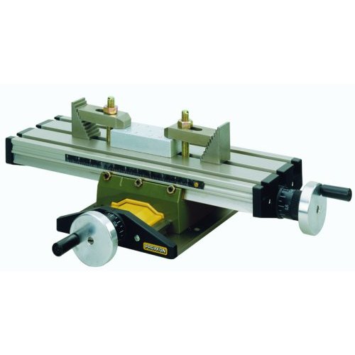
The Proxxon KT 70 stage has rigidity that I may never achieve with my own capentry skill. I think it would make a good second CNC for milling PCBs on 4"x6" copper-clad boards (2oz copper FR4). Folks have already made guides to adapting an MF 70 Proxxon Mill into a CNC so a KT 70 conversion should be relatively straightforward.
Update: 17 August 2010 -- Stepper Driver 1.2 on the Valkyrie CNC
I upgraded the drivers to RepRap Drivers v1.2, and upgraded the power to 24V 13A PSU. They work! More to follow.
/uploads/j/o/john-ny/imported/clone_cnc_august2.JPG


