This post explains the different steps necessary to use a
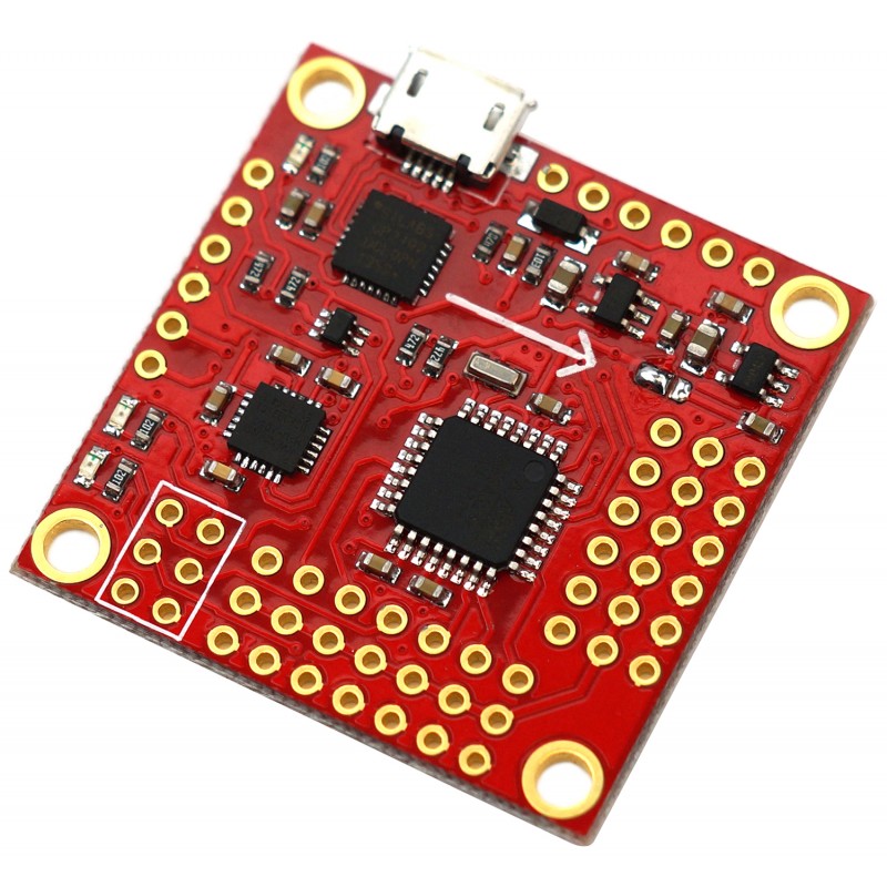
MultiWii compatible board for two axis servo-based stabilization. Many people try to make projects that require stabilization and don't really want to have to worry about programming; fortunately MultiWii comes to the rescue and helps you get this done fast and even at a low cost. The following tutorial will be based on RobotShop's inexpensive
MWC MultiWii Flight Controller for UAV (Arduino Compatible), but any
Arduino with a compatible
accelerometer could be used for this project.
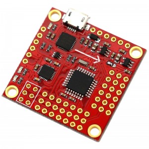 MWC MultiWii Flight Controller for UAV - Front MWC MultiWii Flight Controller for UAV - Front |
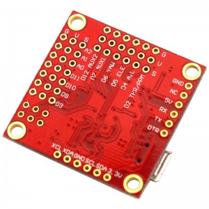 MWC MultiWii Flight Controller for UAV - Back MWC MultiWii Flight Controller for UAV - Back |
"MultiWii" is an
Arduino project that was created to control
multi-copters (such as quadcopters, hexacopters and even planes) and was originally based on the Nintendo Wii hand-held remote's sensor. This project evolved and now features a lot of additional options, and the code has been adapted to work with most major sensors as well. The board we use here includes the MPU6050 sensor from InvenSense which has a three axis gyroscope as well as a three axis accelerometer.
The first thing to understand is that the MultiWii is an Arduino project that is highly customizable, so it needs to be configured to the hardware you use as well as the intended use (flight control, stabilization etc). It's all done in the
Arduino IDE programming environment and for this project there is little to know about it other than how to upload the project to the board.
Here are the steps:
- Download:
- Download and install the USB drivers for your board.
- Download and install the Arduino IDE Software.
- Download the MultiWii_2_3 - MPU6050 - Gimbal - 23-10-2014.zip project and unzip the whole project as it is in a know location on your computer.
- Download and install JAVA if it's not already on your computer (needed for the MultiWiiConf configuration software).
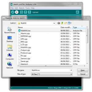
- Open the MultiWii project:
- Open Arduino IDE software
- In the top menu, click on "File" then "Open" and browse to the known location where you unzipped your MultiWii files. There you can search for "MultiWii_2_3 - FLIP - Gimbal - 23-10-2014/MultiWii/MultiWii.ino"
 Arduino IDE - MultiWii - Open Project Arduino IDE - MultiWii - Open Project |
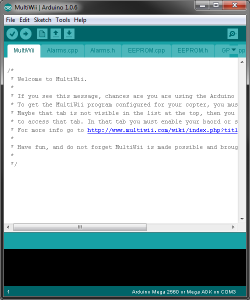 Arduino IDE - MultiWii Arduino IDE - MultiWii |
- Configure Arduino IDE :
- Select the type of board that you have (in our case it is the Arduino Pro Mini w/328)
- Select the COM port for your board (the number may be different from the example shown below)
 Arduino IDE - MultiWii - Board Selection Arduino IDE - MultiWii - Board Selection |
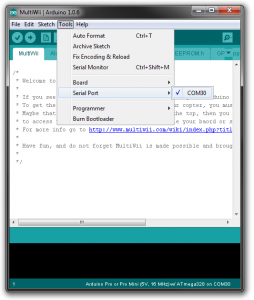 Arduino IDE - MultiWii - COM Selection Arduino IDE - MultiWii - COM Selection |
- Upload the project to your board :
- Click on the arrow pointing "right" just under the top menu of Arduino IDE (shown below in yellow), there should be a progress bar on the bottom with "Uploading" and after some seconds it should say "Done uploading".
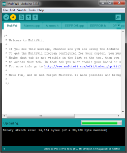 Arduino IDE - MultiWii - Uploading Arduino IDE - MultiWii - Uploading |
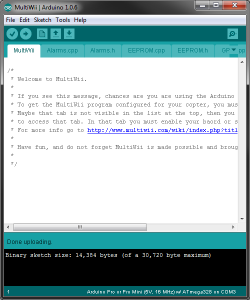 Arduino IDE - MultiWii - Done Uploading Arduino IDE - MultiWii - Done Uploading |
- Connections to the MWC MultiWii Flight Controller (see illustration below) :
- Provide power to the board: it works on 5-6VDC and this supply will power the board as well as the servos. All the GND and +5V pins are linked together on the board.
- Connect the ROLL servo to A1.
- Connect the PITCH servo to A0.
- Connect TRIGGER (if needed, but this requires the use of an RC remote to trigger a camera) on A2.
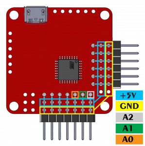 MultiWii_2_3 - MPU6050 - Gimbal - Pinout MultiWii_2_3 - MPU6050 - Gimbal - Pinout |
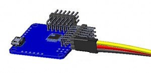 MultiWii - MWC - Usual Servo Connection Top to bottom: Yellow is Signal, Red is +5V, Black is GND MultiWii - MWC - Usual Servo Connection Top to bottom: Yellow is Signal, Red is +5V, Black is GND |
Once all the steps above are done, you should get movement on your servos connected to A0 / A1 when you move your MWC Flight Controller. You can adjust the maximum / minimum movement of each servos as well as the startup position to be optimal for your application.
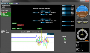
- MultiWiiConf
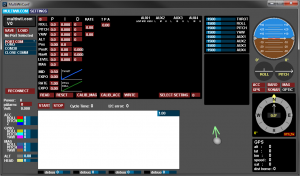
- Open the MultiWiiConf.exe that is located in the same directory that you unzipped your MultiWii files "MultiWii_2_3 - FLIP - Gimbal - 23-10-2014/MultiWiiConf/application.windows32/MultiWiiConf.exe"
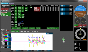
- Select your COM port and click on "START"
- Click on the "SELECT SETTING" button, this will enable the "SERVO" tab near Top Left of the program
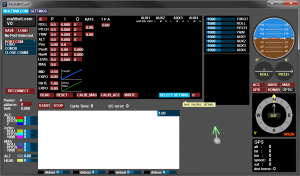
- Click on the "SERVO" tab and once in that page on "GIMBAL"
- Now to change those values, just click in the case and the value will change (like a graph bar).
- MID - Middle starting position
- TILT_MIN - Minimum value for the TILT servo (pitch)
- TILT_MAX - Maximum value for the TILT servo (pitch)
- TILT_PROP - The multiplier between the sensor signal and the actual reaction of the servo
- ROLL_MIN - Minimum value for the ROLL servo
- ROLL_MAX - Maximum value for the ROLL servo
- ROLL_PROP - The multiplier between the sensor signal and the actual reaction of the servo
 Arduino IDE - MultiWiiConf Arduino IDE - MultiWiiConf |
 Arduino IDE - MultiWiiConf - Start Arduino IDE - MultiWiiConf - Start |
 Arduino IDE - MultiWiiConf - Select Setting Arduino IDE - MultiWiiConf - Select Setting |
 Arduino IDE - MultiWiiConf - Gimbal Arduino IDE - MultiWiiConf - Gimbal |
We hope this will get your started with your servo-based gimbal or stabilization project


 MWC MultiWii Flight Controller for UAV - Front
 MWC MultiWii Flight Controller for UAV - Back
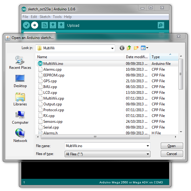 Arduino IDE - MultiWii - Open Project
 Arduino IDE - MultiWii
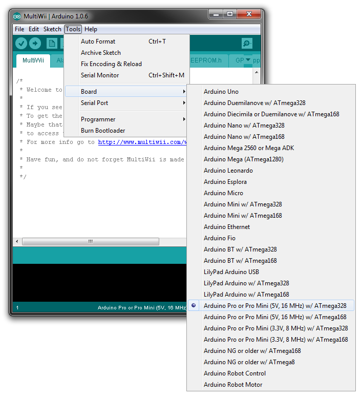 Arduino IDE - MultiWii - Board Selection
 Arduino IDE - MultiWii - COM Selection
 Arduino IDE - MultiWii - Uploading
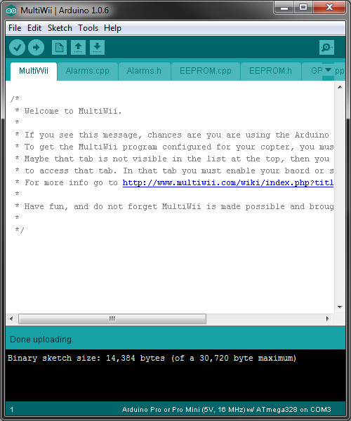 Arduino IDE - MultiWii - Done Uploading
 MultiWii_2_3 - MPU6050 - Gimbal - Pinout
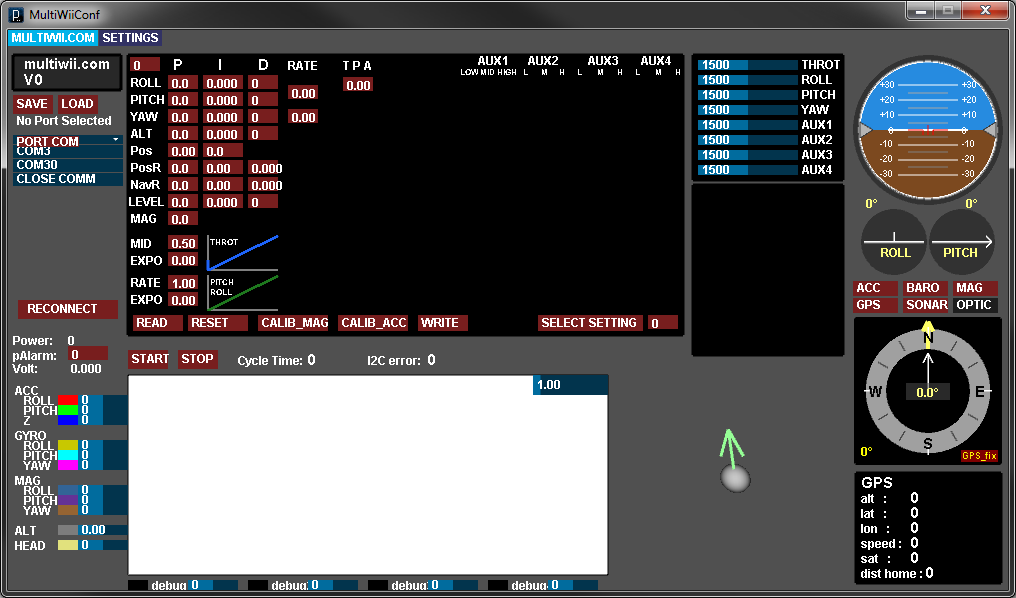 Arduino IDE - MultiWiiConf
 Arduino IDE - MultiWiiConf - Start
 Arduino IDE - MultiWiiConf - Select Setting
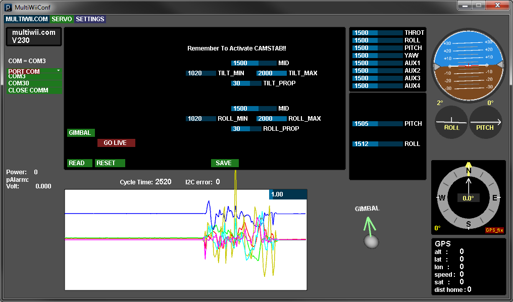 Arduino IDE - MultiWiiConf - Gimbal