

How to synchronise two CMOS Camera Modules for Stereo Vision


It has been a while since my last posting on this topic. In the meantime I made significant progress as you can see here:
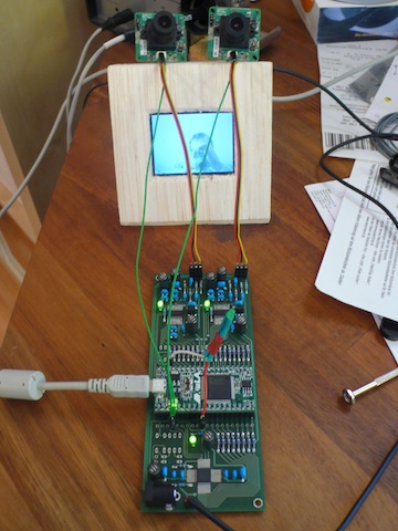
There is now a PCB with all necessary stuff on it which for example completely alleviates all I2C chip configuration problems I had in the past with my first wire-connected prototype. From the number of ferrite beads you see that the design is a little bit paranoid in terms of protecting the ICs from mutual and external interferences. The FPGA daughter board is still a XuLA, but now a XuLA-200 as the preceding model XuLA-50 went out of production. On the test monitor you see not yet a stereoscopic side-by-side live image but the two cam modules are in sync now by hardware. These NTSC/PAL CMOS cameras are available here or here for a reasonable price of $30 or € 30. The way how to do the sync with the modules shall be outlined in this posting.
Initially I had the idea of synchronising the modules by means of hardware programming of the FPGA-board. I created a customized sync pulse for both BT.656 video streams in the FPGA and meade some measurements with an oscilloscope. It turned out that both local clocks on the modules jitter significantly, maybe caused by the low-cost nature of the cams. And jittering clocks is something you don't really want for stereo video processing. I must further admit in this context that my VHLD knowledge is still basic and that I probably missed a good idea to do the syncing of both streams "in software" with adaptive FIFOs or other stuff. So I decided to have a hardware synchronisation by means of injecting the 6MHz clock signal into the cam modules rather than using the two jittering local oscillators. The 6MHz clock signal is created on the XuLA-board.
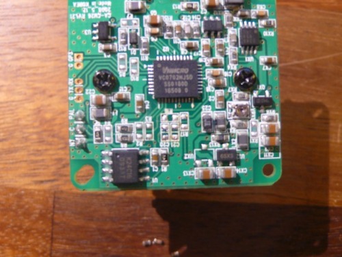
At first I tried to remove the 6MHz crystal with precaution but this attempt was not very successful as you can see in the following photo.
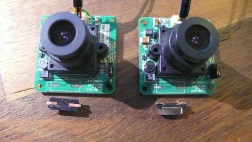
On both camera modules the traces wear out as the PCB material seems to be very sensitive to heat, though my soldering iron was quite small and "SMD-proof". After this flop I noticed that there was no way back to attach the crystals again on the modules.
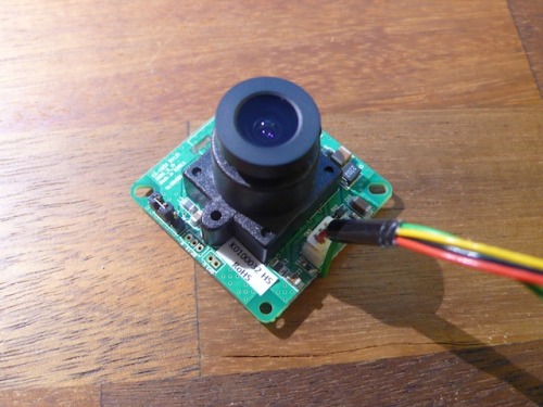
I then inspected the module with an magnifying glass and realised that it is clocked with a standard Pierce oscillator, which means there are beside the crystal some more components left (see this on Wikipedia). But at that time I left all in place. After ripping-of the crystal I attached the CLK cable to the right position which leads directly to CLK-input pin 23 of the Vimicro 0702 chip, for which I have found a datasheet somewhere on the internet.
After feeding the required 6MHz clock signal into the green cable the camera was working again. But the performance was not really flawless. I noticed that keeping the remaining Pierce oscillator components in place might not be a good idea, as the resistors introduce a feedback between CLK-input pin 23 and CLK-loopback pin 24. These components are needed for a crystal but not for an external clock injection. So I just soldered them out.
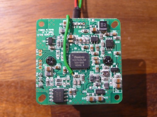
And attached the CLK cable on both modules once again. Notice the attachment location on both boards.
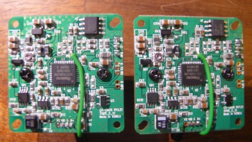
Now both modules are working correctly when supplied with the 6MHz clock signal. I would expect that the video signals should be in syncronisation as both modules see exactly the same clock signal. I am going to check this next week with an oscilloscope.
Cheers,
A.
Thanks for helping to keep our community civil!
This post is an advertisement, or vandalism. It is not useful or relevant to the current topic.
You flagged this as spam. Undo flag.Flag Post
Your post is currently under review by our moderation team. The review process usually takes up to 48 business hours.
You can track your post's status in the "My Content" section of your profile. Once approved, it will be published and visible to others.

Thank you for contributing to our community!