

ESP8266 running NodeMCU as a controller

Every since the ESP8266 modules were released, I have wanted to try one. I ordered a few once they came out last year, but did not get to try them out until this year. After trying one module that seemed to work but never could be connected to, I tried another and was finally able to get one to work. The only test I actually did with it was to grab a webpage, basically a curl call. That was earlier in the year and had done nothing else since with them.
I've seen on the web lots of development going on for the modules. One of the projects that caught my eye was NodeMCU. This loads the board with a Lua interpreter. Development boards available have also grown, with many modules and board types to select from. The one I chose has a ESP–12 mounted on a breakout board giving access to most all of the GPIO pins. This allows for easy access to the pins and makes it easier to reflash the unit.
To find out more about NodeMCU, go to the website. Here you will find lots information on the system and the hardware it runs on. You can get the latest firmware from the Github site for the project. You'll also want a firmware loader and you can get one from the Github site as well.
Currently the flasher only runs on Windows but you may be able to run it on virtual box or Wine. There's also Python tools you can use from the command line to flash it but success mileage may vary with these tools until you initially flash the unit with Node. You'll also need a 3.3 volt serial to USB cable. I use a CH340 switchable adapter which allows 3.3 or 5 volts.
A NOTE on Flashing the ESP-12: GPIO15 needs to be connected to ground as well as GPIO0.
Once you have the unit reflashed with Node, you will want a loader to load your Lua scripts with. The one I use is ESPlorer. It's a java based application and should run most platforms. There is also a Python tool for this as well.
My goal for this mini project is to create A simple autonomous rover with just the ESP and NodeMCU. In looking at the specs for node most of the supporting libraries are already written. GPIO, PWM and Timer libraries are included in the Lua interpreter.
After flashing the board my next step was to write the base code I would use for the bot. To get the initial code syntax checkable locally on my computer, it was nessasary to stub out the NodeMCU libraris not included in normal Lua. I did this by making fake functions for the GPIO and tmr classes. This allowed me to check my code for syntax errors before uploading to the board. After this was done, the code was uploaded and verified with the real Node Lua.
I decided to write the code similar to processing and Arduino code with a setup and loop function. Outside of that, I have four functions and they are as follows; forward, back_up, turn_left and read_usonic. I also needed functions for delays but could not use the built-in delay in the library as it is a blocking function. Inside the tmr class there is a tmr.now() method that is similar to millis in the Arduino world. So I created two functions one to delay in milliseconds and one in microseconds. There's still another gotcha here, the processor has a watchdog timer so when you're doing long loops or other long processes that block or could block you need to clear the watchdog timer, in which there is a method for this. Keeping that in mind and not blocking for very long you should be able to little live happily with a little processor.
The first motor drive functions I wrote just drove the H bridge directly with GPIO writes to the pins with a high or low based on what was needed to the drive direction. After doing this and getting a general sense that it would work, I changed the drive functions to use the PWM library functions. Now for another gotcha. Most GPIO pins can be setup as a PWM but you're only allowed to have three pins set as PWM at any one time. Luckily you can redefine pins as you need them during run time, so to overcome this problem I only keep two pins defined as PWM at any one time. For most little robots this should be fine.
My next step is to get the ultrasonic sensor working. I need to do A little soldering and add a resistor to the echo line to knock the 5v down to around 3v. Then I can test my sensor function.
I will update this blog as progress is made.
NOTE:
- If you are using batteries to power the module, you may notice strange things after the battery drops low in voltage. It may return errors for code that worked 2 seconds earlier or you start getting comm garbage or errors.
- If you get time outs whilst sending the lua script to the module, you may need to increase the time-out value on ESPlorer or your tool of choice. Increasing the line send time may help as well.
Here is a little video of the code in action.
UPDATE 04/01/2015
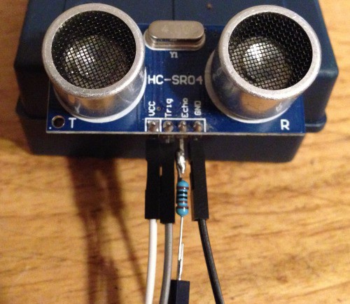
Soldered up the HC-SR04 with the 1k resistor and hooked it up to the ESP. I used an Arduino for a 5v power supply for the sensor.

A quick code test shows it mostly works, though I need to do some negitive bounding in the function. It does look promising!

As of now this is how the code looks... Please remember this is very much an alpha project.
--
-- Simple object avoider robot using the ESP8266/Nodemcu ESP-12
-- Using a L9110s h-bridge and an hc-sr04 with a 1k resistor
-- on the ECHO pin.
--
-- The current ESP only allows for 3 active pwms at any one time.
-- We get around this by the fact we only need 2 at any time. Each
-- direction change resets them pins used as pwm.
--
-- Written by Scott Beasley 2015
-- Open and free to change and use. Enjoy.
--

function setup ( )
   gpio.mode (2, gpio.OUTPUT) -- ia1     - GPIO4
   gpio.mode (3, gpio.OUTPUT) -- ia2     - GPIO0
   gpio.mode (1, gpio.OUTPUT) -- ib1     - GPIO5
   gpio.mode (4, gpio.OUTPUT) -- ib2     - GPIO2

   gpio.mode (8, gpio.OUTPUT) -- trigger - GPIO15
   gpio.mode (7, gpio.INPUT)  -- echo    - GPIO13

   -- Halt, just in case...
   halt ( )
end

function loop ( )
   local distance = 0
   local command = 0
   local timestart = 0

   distance = read_usonic ( )
   -- Go forward until an object is 5cm or less
   if (distance > 5) then
      forward ( )
   else
      back_up ( )
      turn_left ( )
   end

   -- Do something to yield to the system a bit.
   tmr.wdclr ( )
   delay_ms (80)
end

function read_usonic ( )
   local pulse_start = 0
   local pulse_end = 0

   -- Send out the trigger signal to the sensor
   gpio.write (8, gpio.LOW);
   delay_us (5)
   gpio.write (8, gpio.HIGH);
   delay_us (10)
   gpio.write (8, gpio.LOW);

   -- Wait for echo to go HIGH
   while (gpio.read (7) == 0) do
      tmr.wdclr ( )
      pulse_start = tmr.now ( )
   end

   -- Wait for echo to drop LOW again
   while (gpio.read (7) == 1) do
      tmr.wdclr ( )
      pulse_end = tmr.now ( )
   end

   -- Return centimeters
   return ((pulse_end - pulse_start) / 58)
end

function back_up ( )
   --gpio.write (2, gpio.LOW);
   --gpio.write (3, gpio.HIGH);
   --gpio.write (1, gpio.LOW);
   --gpio.write (4, gpio.HIGH);

   set_pwm_on_pins (3, 4)
   pwm.setduty (3, 200)
   pwm.setduty (4, 200)

   delay_ms (500) -- Delay 500ms
   halt ( )
end

function turn_left ( )
   --gpio.write (2, gpio.LOW);
   --gpio.write (3, gpio.LOW);
   --gpio.write (1, gpio.HIGH);
   --gpio.write (4, gpio.LOW);

   set_pwm_on_pins (1, 4)
   pwm.setduty (1, 200)
   pwm.setduty (4, 200)

   delay_ms (500) -- Delay 500ms
   halt ( )
end

function forward ( )
   --gpio.write (2, gpio.HIGH);
   --gpio.write (3, gpio.LOW);
   --gpio.write (1, gpio.HIGH);
   --gpio.write (4, gpio.LOW);

   set_pwm_on_pins (1, 2)
   pwm.setduty (1, 400)
   pwm.setduty (2, 400)
end

function halt ( )
   pwm.stop (1)
   pwm.stop (2)
   pwm.stop (3)
   pwm.stop (4)
   pwm.close (1)
   pwm.close (2)
   pwm.close (3)
   pwm.close (4)
   --gpio.write (2, gpio.LOW);
   --gpio.write (3, gpio.LOW);
   --gpio.write (1, gpio.LOW);
   --gpio.write (4, gpio.LOW);
end

function delay_ms (milli_secs)
   local ms = milli_secs * 1000
   local timestart = tmr.now ( )

   while (tmr.now ( ) - timestart < ms) do
      tmr.wdclr ( )
   end
end

function delay_us (micro_secs)
   local timestart = tmr.now ( )

   while (tmr.now ( ) - timestart < micro_secs) do
      tmr.wdclr ( )
   end
end

function set_pwm_on_pins (pin1, pin2)
   -- Close off pwm on pins to free them up
   pwm.close (1)
   pwm.close (2)
   pwm.close (3)
   pwm.close (4)

   -- Set the pins sent in as pwm
   pwm.setup (pin1, 500, 512)
   pwm.setup (pin2, 500, 512)

   -- Start up the timer on pins
   pwm.start (pin1)
   pwm.start (pin2)
end

-- Function to test the delays with
function blink ( )
   gpio.write (2, gpio.LOW);
   print ("on")
   delay_ms (1000)

   gpio.write (2, gpio.HIGH);
   print ("off")
   delay_ms (1000)
end

-- Run the bot code
setup ( )
while (1) do
   loop ( )
end
Thanks for helping to keep our community civil!
This post is an advertisement, or vandalism. It is not useful or relevant to the current topic.
You flagged this as spam. Undo flag.Flag Post
Your post is currently under review by our moderation team. The review process usually takes up to 48 business hours.
You can track your post's status in the "My Content" section of your profile. Once approved, it will be published and visible to others.

Thank you for contributing to our community!