

Cheap 40W Laser Engraver from China

I have wanted a laser engraver for quite some time but the price has always been prohibitive for me. Recently though, I found some engravers from china on Amazon for about $500.00 USD and free shipping. Plus, I contacted the vendor and found that the unit would ship from California. I read all the reviews and they all agreed that the machine is great. However, the downside of these machines was the software that is included. After carefully considering all the relevant information I decided to purchase one.
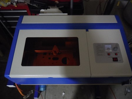
The machine arrived in two days and to my dismay the packaging was damaged. Upon unboxing the machine I discovered that the window was damaged. I contacted the vendor and they offered to give me $50.00 back and I keep the unit, or I could return it and they would send another. I told them that I would test the unit out and then, if there were no other issues, I would decide which option I would pursue. In the end, everything worked well and I decided to keep the unit and accept the partial refund. Below is a picture of the unit.

Edit 12/30/2015:
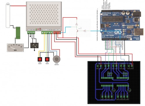
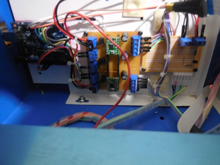
Above is a drawing of how I wired my laser engraver. I did not include the connections for the stepper motors as this information is available at the link listed above. This drawing represents the things that I did differently from the folks at Adventures in DIY Engineering. As mentioned before the stepper driver breakout board (shown with the black background) is one that I created myself and accepts A4988 driver modules. I used this instead of the RAMPS 1.4 board that the ADE folks used. It is a very simple board that I isolation routed on my mini cnc mill. I can provide the Eagle files if anyone really wants them.
Using the system the way that I have it setup comes with special challanges. For instance the software that I use to generate G-code is CAMBAM and it requires some manual editing after generating the code. This is because I have to change the Z commands to M codes to turn on and off the laser. I use the spindle speed command Sxxx to control the laser power. Although the S command is capable of a range from 0-30,000...in this application S1000 represents 100% laser power and increasing the spindle speed above 1000 has no additional benefit. S100 = 10%, S200 = 20% and so on up to S1000 (100%).
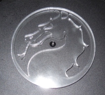
I use my machine for cuting out shapes and it works very well for that. I have not spent any time trying to etch raster graphics, so I dont know how well it will do for that. In any case I hope that this information will be helpful!
Thanks for helping to keep our community civil!
This post is an advertisement, or vandalism. It is not useful or relevant to the current topic.
You flagged this as spam. Undo flag.Flag Post
Your post is currently under review by our moderation team. The review process usually takes up to 48 business hours.
You can track your post's status in the "My Content" section of your profile. Once approved, it will be published and visible to others.

Thank you for contributing to our community!