

Arduino PID Motor Controller

LINKS TO LEARN :
http://forum.arduino.cc/index.php/topic,8652.0.html
http://forum.arduino.cc/index.php?topic=13269.0
http://www.billporter.info/2010/08/07/sagar-update-new-motor-controller-and-motors/
http://www.billporter.info/2010/01/01/s-a-g-a-r-s-smart-motor-controller/
Download the EAGLE Schematics, Board Layout and code from here:
https://drive.google.com/open?id=0B8lxGSgwuFtYfjVLZHhINUt2cW1taFBDYndudkV6R0xLXzhKR1lRNWRQTVZYOVA1ek5NVk0&authuser=0
Watch the video at:
https://youtu.be/yi4Pl8ZOBXM
INTRODUCTION :
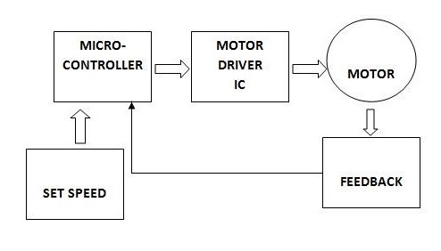
The development of high performance motor drives is very important in industrial as well as other purpose applications. Generally all high performance motor drives use quadrature encoders and PID control because of its simplicity and precise control. The quadrature encoder acts as a feedback from the motor, it is connected to the microcontroller for furthur processing.
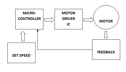
With the use of Arduino, l298N and Optical Quadrature Encoder we can drive the dc motor at desired speed having a feedback loop and in this project we have used proportional integral and derivative method in which errors are not only solved but also taken to its minimal value with very low amount of error oscillations.
PROPORTIONAL CONTROL:
The proportional part of PID examines the magnitude of the error and it reacts proportionally. A large error receives a large response
INTEGRAL CONTROL:
To address the first issue with the proportional control, integral control attempts to correct small error (offset).
DERIVATIVE CONTROL:
The derivative part of the control output attempts to look at the rate of change in the error signal. Derivative will cause a greater system response to a rapid rate of change than to a small rate of change.
Visit the below link to gain knowledge about PID control.
http://ctms.engin.umich.edu/CTMS/index.php?example=Introduction§ion=ControlPID
Quadrature Encoder :
The below link shows the working of a quadrature encoder, please visit the link.
http://www.dynapar.com/Technology/Encoder_Basics/Quadrature_Encoders/
The below link shows all about rotary encoders, please go through the link to gain knowledge.
http://en.wikipedia.org/wiki/Rotary_encoder
Materials Used :
- 1 300 RPM Geared Motor.
- 1 L298N Motor Driver.
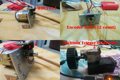
- 1 Slotted Encoder Disk (32 slots).
- 2 MOC7811 Optical Slotted Interrupters.
- 2 10 K Resistors.
- 1 220 Ohm Resistors.
- General Purpose PCB.
- 1 Arduno UNO.
- Connecting Wires.
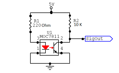
The Image below shows the circuit diagram of MOC7811 Optical Encoder, We need to make 2 circuits as we are making a quadrature encoder. SignalOut pin of bothe MOC7811 should be connected to pin 2 and 3 of arduino as these are interrupt pins of the arduino.
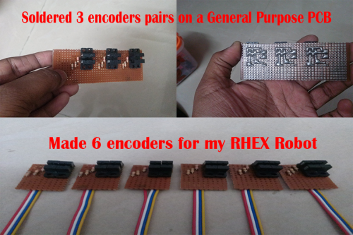
Solder the encoders on a general purpose PCB as shown below.
You can add Schmitt Trigger IC CD40106 so as to convert the output of encoders into pure square wave. Connect MOC7811 output to Vi in the below circuit and connect bthe Vo to arduino. There was not much significant difference even after I added the schmitt trigger.

https://www.youtube.com/watch?v=yi4Pl8ZOBXM
Thanks for helping to keep our community civil!
This post is an advertisement, or vandalism. It is not useful or relevant to the current topic.
You flagged this as spam. Undo flag.Flag Post
Your post is currently under review by our moderation team. The review process usually takes up to 48 business hours.
You can track your post's status in the "My Content" section of your profile. Once approved, it will be published and visible to others.

Thank you for contributing to our community!