

Arduino Nano on PCB

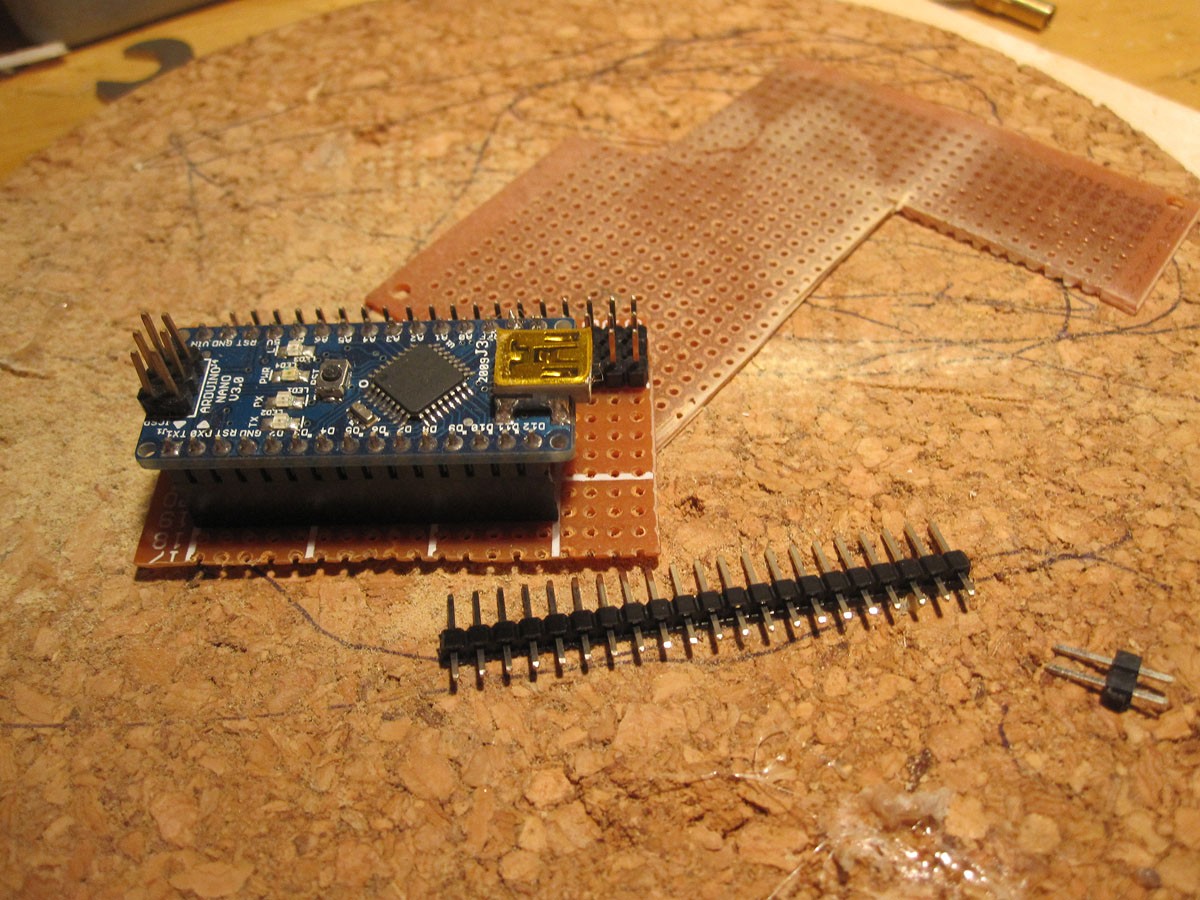
As I wrote in Chopstick Junior 1.0 (there you can see it in the robot) here comes the part with the Arduino Nano on a PCB.
Why I did this?
Well, it's just a try to use the Arduino Nano for other robots too. This gives me the chance to remove the MC and put it in another robot or just upgrade this one with a new Nano. But the most important is that I can connect all the servos I need directly to the board without any solering or using male-to-female cables.
However, the reason ist not the important thing here, but how to do it.
First thing was cutting a matching piece of PCB, male and female header pins and some wire.

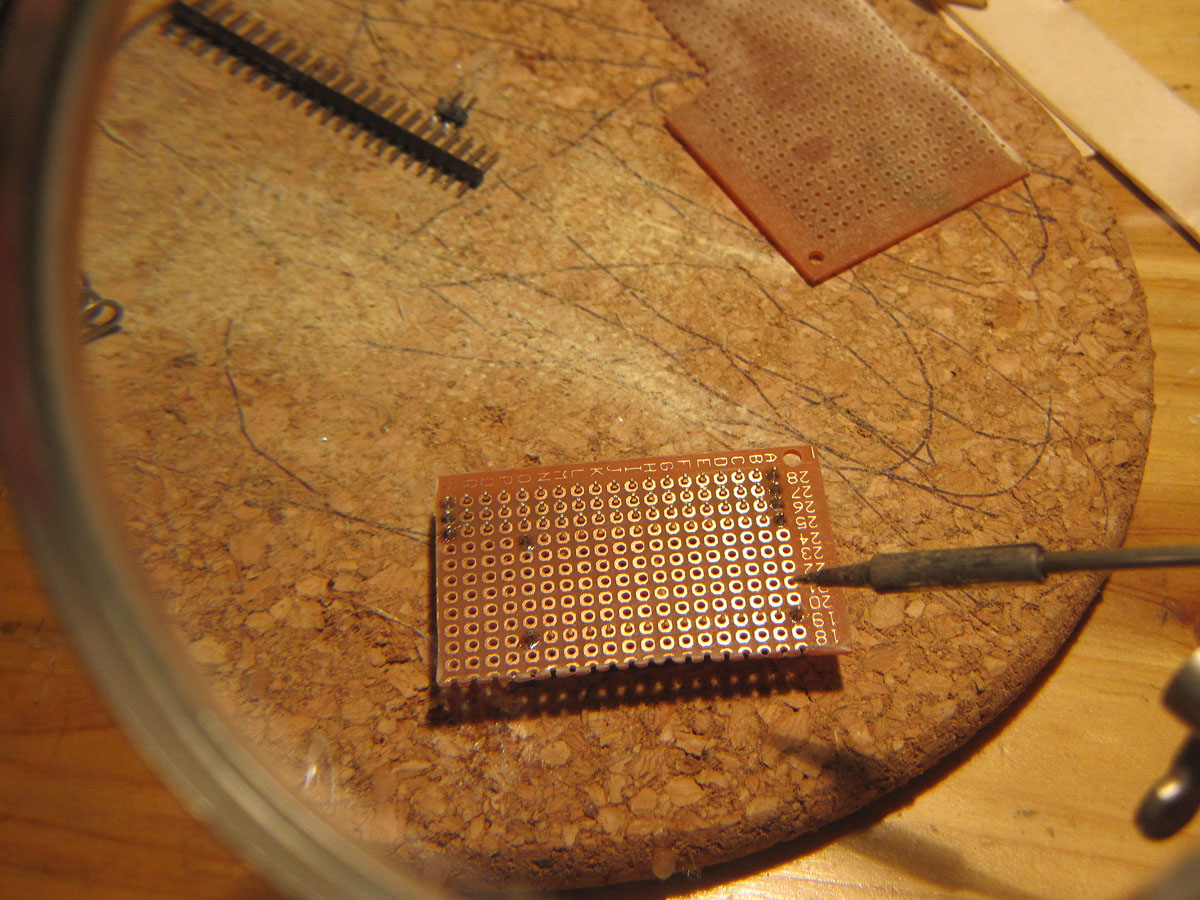
Then solder the header pins on the PCB.
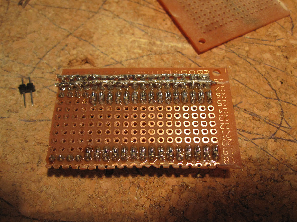
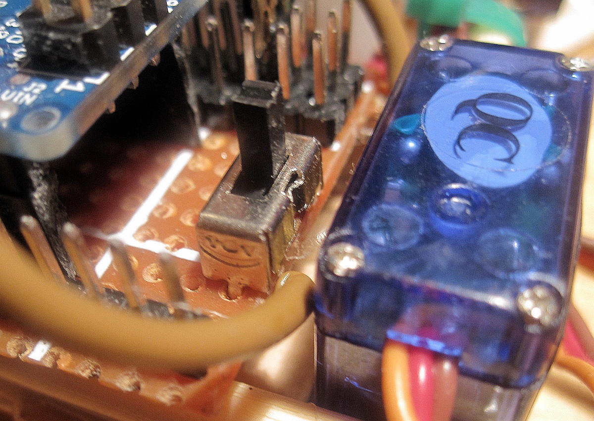
As you can see on the right picture above there are two heavy duty power lines. I soldered a thick wire over the whole lenght of the power supply line (for the servo connectors) to make sure that enough juice is coming trough. The other solder points are the in/outputs of the Arduino Nano just pull them out to the female header pins.
Then solder two smaller wires to the power lines and then to the ground and 5V pin on the Arduino Nano to supply it with power as well.
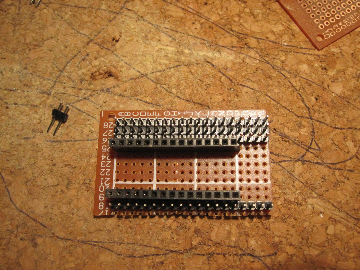
This is pretty much all I've done. For the current project I do not need more.
There is a lot of ways to put more on the PCB if needed but for this time this should be all. Just plug the MC in now and make a very easy servo connection and power supply.
UPDATE:
I soldered a power switch on the board. Next thing to do is to add a 555 timer chip for several tasks.
Thanks for helping to keep our community civil!
This post is an advertisement, or vandalism. It is not useful or relevant to the current topic.
You flagged this as spam. Undo flag.Flag Post
Your post is currently under review by our moderation team. The review process usually takes up to 48 business hours.
You can track your post's status in the "My Content" section of your profile. Once approved, it will be published and visible to others.

Thank you for contributing to our community!