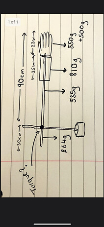
“Counter-torque” needed to keep the arm horizontal against gravity would be:
0.535Kg x 45cm (assuming the mass is centered) = 24.075 Kg-cm
0.81Kg x 50.5cm (90-22-35/2) = 40.905 Kg-cm
0.55Kg x 79cm (90-22/2) = 43.45 Kg-cm
0.5Kg x 90cm = 45 Kg-cm (payload?)
Add them up to get 153.43 Kg-cm. However you show there’s a mass on the opposite side:
0.264Kg x 15cm (30/2) = 3.96 Kg-cm
Therefore the torque needed at the pivot would be:
153.43 Kg-cm - 3.96Kg-cm = 149.47 Kg-cm (let’s round it to 150 Kg-cm)
If you wanted to raise the arm, the pivot would need to produce more torque than 150 Kg-cm to produce a change in velocity (i.e. acceleration). To calculate that torque is more involved since the equation is Torque = (Moment of Inertia) x (Angular Acceleration). A slow acceleration involves less additional torque.
Moving 45 degrees in one second doesn’t actually directly give you acceleration (radians per second per second) but rather the average angular speed. The harder part tends to be calculating the total inertia of the system.
Effectively the inertia of each of the masses (and the support rod). Assuming the motor is not rotating at high speed (and it’s not a flywheel), its effect on the inertia is likely to be minimal so it’s up to you if you want to estimate it and include it. Remember, even with all the calculations, it’s best to multiply the calculated value by a “safety margin” to account for inefficiencies etc.
When it comes to inertia formulae, it’s dependent on the shape, the rotation, where the weight is located etc. You’ll need to look it up for each unfortunately. Example
Note that the formula I = (m*r^2)/2 is associated with a disk rotating about the center, which is not the case in your drawing (no disk). You’ll likely be using the formula for a “rod”, “plank” or “satellite”. In inertia equations, “R” is associated with the object’s radius, whereas “L” is the length from the axis of rotation to the center of mass of the object.
Provided the arm is horizontal to the ground, the torque needed is only a factor of the acceleration needed. If you really want to do the calculations, it’s back to Torque = (Moment of Inertia) x (Angular Acceleration).
You’re getting into understanding how to use equations for moment of inertia, which is beyond the tutorial here. It took a chapter in Physics to understand the concept of inertia and the corresponding equations, so it’ll be best to do some background reading outside of this tutorial to ensure you get things right
Normally the shoulder servo requires the most torque, followed by the elbow, then the wrist and the base comes in last. For example on the AL5D, each servo can provide up to:
Shoulder: 24.7 Kg-cm (even at this torque, it’s still largely the limiting factor in the arm’s max payload)
Elbow: 13.2 Kg-cm
Wrist: 9.6 Kg-cm
Base: 6.4 Kg-cm
However that means the arm cannot be rotated vertically since the base would then be responsible for lifting the weight of the arm which it cannot do.
Oh interesting, I assumed the base will need the most torque.
However from my calculations, the shoulder needs around 19Nm of torque and the base only needs around 1.8Nm of torque. So I wanted to make sure that the calculations seem ok.