

Fantastic!! That is amazing… super cool ! I have the c code for walking @cmackenzie that I had used on mine. I am very much tempted to see if that can be ported. I will message you regarding this. I think we should have a catch up soon.
1 Like

@kurte - Ok i know what i did wrong that that time. Last Friday i had another modification to do and update on Arduino library manager. Seems like the last time i didn’t updated the tag inside the library so it was not picked up.
It is now, as well as my change.
Sure is quiet up here (  )
)
I hope everyone is doing well and that you all have a nice (safe) Holidays!
2 Likes
@kurte - It is certainly quite here.
Hope you are all safe and with that new Variant around… stay safe.
2 Likes
Ditto - happy holidays and stay safe 
3 Likes
Hello All,
Hope everyone is keeping safe. Wishing you all a very happy new year!!
3 Likes
Happy Holidays & New Year! @cmackenzie has been advancing with ROS 2 and has/will involve @madmax. The latest firmware update (under Experimental) seems to be working well. Hopefully video updates will be posted soon.
1 Like
A lot of code changes lately and the walking is looking much smoother! Yes, smooth but slow…I’ll turn the speed up soon enough.

3 Likes
Happy New Year all, hope you are all doing well and healthy.
Any updates on this?
Was a guru able to fix the packet reliability issue?
Nice work on the ROS2 stuff.
Are you using any of the timed moves and the like or are you sending out servo packets as fast as possible?
Again happy new year.
@cmackenzie is looking for opinions / ideas about control options using the Radiolink RC remote.

Brainstorming (so feel free to suggest alternatives and give ideas / insights etc.):
Nomenclature
- Throttle (THR): Left joystick up/down (analog) - spring recenter
- Rudder (RUD): Left joystick left/right (analog)
- Aileron (AIL): right joystick left/right (analog)
- Elevator (ELE): right joystick up/down (analog)
- Three way switch (3WL) (left)
- Three way switch (3WR) (right)
- Toggle switch (TSL) (left)
- Push Button (PBR) (right)
RC
- THR: Forward/Backward (ideally mixed with RUD and proportional)
- RUD: Rotate CW/CCW (ideally mixed with THR and proportional)
- AIL: Body roll
- ELE: Body pitch
- 3WL: Future use (ex. 3 positions for body height)
- 3WR: Future use (ex change walking gait tripod / adaptive / ripple)
- TSL: Future use (ex. Reset position / home)
- PBR: Future use (ex. enable terrain adaptation)
Computer
- THR: Keypad W, S or Numeric keypad 8, 2 (not proportional)
- RUD: Keypad A, D or Numeric keypad 4, 6 (not proportional)
- AIL: Keypad arrows up/down or Numeric keypad 7, 9 (not proportional)
- ELE: Keypad arrows left/right or Numeric keypad 1, 3 (not proportional)
- 3WL: Future use (walking gait tripod / adaptive / ripple)
- 3WR: Future use
- TSL: Number 5
- PBR: Future use (ex. enable terrain adaptation)
We don’t need to use all joysticks / switches.
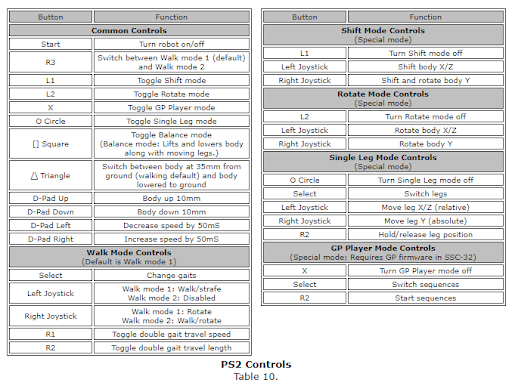
PS2 Reference with Phoenix code (if it helps):

There was a previous idea about using a PS4, which offers additional input (four left and four right buttons), and instead of a three position switch on each side, there are two way switches. A PS5 controller seems very similar to a PS4.
Colin did additional testing with the latest experimental firmware and found no errors. It may be best to proceed using EM0 for the moment while our developers explore improving EM1. Colin can explain what he’s doing more.
1 Like
Are you using any of the timed moves and the like or are you sending out servo packets as fast as possible?
I am not using EM1 at all. I really like how EM0 mode works and I can get the higher level controllers in ros2_controls to plan motion more wholly and since my end goal is robot compliance I need the EM1 motion control disabled. My current control loop is 18 servos at 50Hz and 1Mbps serial and setting position and effort, and reading position, velocity and current (effort). I’ve run it for weeks 24/7 and I don’t see any errors. I’ve run the loop up to 100Hz and verified in the Saleae that it’s good. I moved back to 50Hz because I had other bottlenecks in my ros2 code making 100Hz useless…but even those are gone now so buckle up Ms. Daisy! This is a far cry from the previous per-servo request/response but it does mean constraints on how the multi-servo requests are sent.
Maybe give EM0 a try. You might even be able to get extra smoothness by doing your own motion. My motion is smooth atm. Orocos KDL (C++ lib) does all the IK, and most of the motion planning for me.
3 Likes
We’re starting to brainstorm a new electronics board intended to be a HAT for the Raspberry Pi and would like your input / feedback.
Primary functionality
- Allows for a single power source to be used for a robot (powering servos, RPi etc.)
- Allows the Pi to control LSS servos
- Ideally also compatible with NVidia Jetson Nano (mechanically and electrically)
- Not intended to be “stand alone”, nor replace a Teensy breakout to LSS, nor replace the LSS Adapter.
- Can be used on Lynxmotion SES V2 robots like the hexapod, quadruped, humanoid
Components (minimally)
- Battery input (The LSS Adapter uses an XT60 because it’s a popular LiPo connector)
- LSS Connectors (each connector can theoretically handle 2A, and one HT1 can consume ~1A at 25% load)
- Logic level conversion (RPi operates at 3.3V, LSS bus is 5V)
- 2x20 pin header (RPi standard)
- RC PPM input (to be able to connect an optional standard RC PPM receiver: PPM / 5V / GND) Example
- LEDs: serial Tx, Rx, PWR
- Step-down voltage regulator (assuming 3S LiPo or 12V NiMh / Lead acid): ideally slightly above 5V and ideally >3A (4A+)
Questions
- Add an onboard IMU? Pinout for a separate I2C IMU? 6-axis or 9-axis (i.e. includes compass)? 3.3V or 5V operation?
- Add a (single) resettable fuse after the main battery?
- Use several serial busses from the RPi or just one?
- Pins to power external devices (3.3V, 5V, VIN) and GND?
- Voltage monitoring (Vin)?
Other ideas? Considerations? (Examples below)
- LED, RGB LED or neopixel connected to RPi pins for effect / status / user selected?
- 3.3v or 5V 3-pin headers (S/V/G) to add sensors
- etc.
@cmackenzie @kurte @geraldinebc15 @xan @zenta @scharette @cyberpalin @madmax @dickel
1 Like
Great to hear @cbenson! I was thinking I’d need to make one myself. Here is what I already had compiled for my wish list.
- Based on Compute Module 4 (to keep the it small and light but I also think it depends on availability of Computer Modules now)
- powerful enough switching regulator to power the Rpi from a 12v battery
- Lipo Battery charging circuit
- Teensy-like ARM32 (probably just a header mount)
- Fan PWM for RPi chipset
- RPi power button (momentary)
- RPi doesnt have a clean way to shut down…so if a hard-break power switch or pulling the battery will only lead to corruption of SD card fast
- Small 0.96" OLED or so (bootup status, robot state, etc)
…and last but not least…a low-cost CPLD based device for signal routing! This would be used to provide logic-level switching between 3v and 5v but primarily be to interface peripherals between the RPI (or teensy), especially the LSS ports. So like the LSS Adapter board it would have about 6 LSS ports but they are not connected together. Instead each of the LSS ports goes to the CPLD. The 4 serial ports of the RPi4 would also go to the CPLD, as would the Teensy. Now the RPi can set a register on the CPLD to determine where each LSS port is connected, you can connect all LSS ports into a single serial port, or connect some LSS ports to dedicated serial ports on the RPI or the Teensy instead. It could also route a dedicated RPi serial to a single LSS port for non-LSS stuff like a serial GPS.
The XC9572 CPLD is one I’ve used a number of times, it’s cheap at about $1.70 in quantity and easy to program. I feel like there is probably cheaper and more recent CPLDs out there though. FPGA could work too, but I feel this feature is more suited to simpler CPLDs than a FPGA. I can help here to create the Verilog code to program the device and write the linux driver to configure the routing.
1 Like
Sorry I thought I responded earlier to this, but probably started message and forgot to send
Again hope everyone is doing well and having some fun (and staying safe)
For now I sort of lost steam and put all of this stuff on hold.
Was curious about the follow on to LSS and your new smart servos. The EM=1 stuff looked interesting as it feels very much like a follow on to the old LSS stuff and the SSC-32.
As mentioned could probably get things to work with EM=1 and have host do the interpolation.
Glad you are coming up with a ROS2 solution. Will continue to follow on to see your progress.
Some reason I have difficulties with the idea that there are no messages which become corrupted when using EM=0 when run at 50hz for days, but I was seeing a significant number of them with EM=1 at low number of messages per seconds (like only a few). But weirder things have happened.
Again it is all going well, and I have continued to monitor this thread.
Again hope everyone is doing well and having some fun (and staying safe)
You too of course! Fingers crossed that the healthcare system will return to something more “normal” and Omicron will be less virulent so we can return to something more “normal”.
The EM=1 stuff looked interesting as it feels very much like a follow on to the old LSS stuff and the SSC-32.
Indeed, though the firmware team has been on other priority projects. Hopefully everyone’s servos have been updated to the latest experimental firmware via the LSS Config interface.
When it comes to EM1, we’ll need to review how customers expect it to behave (especially if many signals are being received before it reaches the first position which it received).
Colin has been sending videos to update us privately but hope he’ll share more of his progress here.
@cbenson Sorry I am late on responding to this one as well:
As for a hat for RPI, to me that really depends on what your goals are:
That it you could go extremely basic. That is if you are wanting the RX/TX pins to drive servos, you can simply add level shifters for those two pins. You could decide if they are bidirectional or unidirectional.
You could put on power management to feed through the power pins. I have done that and did not notice any issues, but…
It was not clear to me earlier when I was playing with RPI hats and first ROS stuff, if powering the RPI through the expansion connector was considered safe or not or if it bypassed some of the power circuitry of the RPI…
I also hacked it by using an external BEC which converted the 12v to 5v, which I then wired into the power port of a powered USB Hub. This was a real hack, but I then plugged the RPI into the HUB twice, once as the source and once as a output. The output one plugged into it’s power port. This worked on cheap hub, but some others not who would not power up the destination ports until it received USB signal… Another option was to have a connector on the hat that you plug in a cable which then plugged into the RPI power port.
Or you could go whole hog and do something like I did maybe 4-5 years ago and add a nice micro-controller to it with lots of features.
This one has a T3.6 and has on it about that many years of dust  It was on my desk as using it to do some MTP testing.

This was one I used on RPI and/or Odroid and/or UP board…
This was setup for Bioloid AX servos and it had my normal board building, that you can not leave any square tenth of an inch unused  It was setup to convert the 3.3v outputs to 5v for servos…
I used a barrel connector which I connected either wallwart or had connector to 3S lipo.
I was using a Pololu DC-DC converter which could fee through to RPI through 20 pin connector. Plus the double row of pins below the RPI connector (at top in this picture) was a set of jumpers to use shunts to decide which pins to connect from the teensy to the RPI, and lots of IO pins with 3 pin headers…
The larger transistor toward bottom left was to allow me to be able to switch servo power on and off. Resistor divider circuit to detect battery voltage…
Plus a simple sound circuit and one Noepixel… Some of the boards I had setup to be able to extend that Neopixel to more than just one.
Note: I probably still have an earlier t3.2 version sitting around here as well. And I know at one point was working on T4.x version…
For most things this board was probably overkill.
When I was experimenting with this, it was unclear if you were better off with using the
Serial pins on expansion or sticking with USB… Issues with at least earlier RPI boards that only one of the two uarts was really a UART and by default it was assigned to BT…
Also unclear how much of the work you are wanting to put on the HAT. For example if EM=0 was the main way to talk to the servos, I would probably have my own higher level communication, that said move all of these servos to this position over time X and I would let the hat take care of all of the outputs and inputs from servos and free up the RPI to do other things. If not doing that than again maybe just go direct from RPI pins to level shifers…
Also unclear if your main goal is for something like ROS2 and you are adding reasonable computing power, if you want the board to be tightly coupled/dependent on a host like an RPI or if you wish to make it run independent and for example maybe have ethernet stack which then allows you to directly have this device source and listen to ROS topics…
Not sure if this helps you or not, but good luck!
1 Like
It does help indeed! Took note of all main points raised. A Pi HAT seems to be the logical solution to use to interface the RPi 3 / 4 to the LSS servos and an external battery. It makes sense to have voltage regulation onboard and power the Pi via the 2x20 header.
{…} tightly coupled/dependent on a host like an RPI or if you wish to make it run independent
That is an interesting question indeed. To run ROS-based code, it will more than likely need to be stacked and make full use of the Pi, but for basic motion, something like the ATMega328 was able to run the Phoenix code. Ultimately we’ll need to see just how much added versatility the smart servos can provide for modular robots like a humanoid, quadruped, hexapod.