

Thank you!
One more thing - is there a list of commands that are defined in the Arduino LSS library and their descriptions? A webpage or a PDF would be nice.
Thank you!
One more thing - is there a list of commands that are defined in the Arduino LSS library and their descriptions? A webpage or a PDF would be nice.
The majority of commands can be found here:
If you’re able to define a baud rate and use the serial output command, you’re pretty well set up to use the LSS protocol directly and don’t necessarily need the library.
I was hoping the LSS library would automatically add the syntax formalities of # and \r etc.
Have you found that it does not? For example, println includes a carriage return.
As @cbenson mentioned, you can use O and CO to set the origin (or offset) of the LSS. If used without a value, O/CO will use the current position as a zero. Please note that if your virtual angle is < -180° or larger than 180° during a power cycle, the angle when starting will be set to a value in the range of [-180°, 180°].
Using the O/CO commands will update variables “live” and you can keep using your servo without a reset.
As for CW/CCW, the G/CG commands only change which direction are the positive & negative direction of the angle. You can always move in both direction using D (move to absolute position) and MD (move to relative position, a delta) commands.
Yes it does.
The function definitions are available here.
You should definitely check out the examples found here.
I hope this info helps a bit!
Thank you for all your help so far.
One more question - I am using an Arduino Mega 2560 which has 4 hardware serial ports. Can I use any of them (in pair) for the LSS Adapter or does LSS insist on Pin 0 and Pin 1? I would think LSS would be blind to where the data is coming from/going to correct?
No problem! 
I’m watching on a few sections and tags, so I usually at least read most LSS posts…  But, if you make a new topic and need help related to the libraries or software, feel free to @ me and I’ll answer when I can.
Indeed it does!
In theory - and from a software point of view - any of them can be used with the Arduino LSS library (it can use any serial objects, including SoftwareSerial ones!).
The bus is hard-wired to the single hardware serial port of the regular Arduino board design, thus pin 0 & 1.
That being said, there are a few options you can go for, such as:
 ).
).Sincerely,
I know about the options on an Arduino Uno. I was specifically asking for Arduino Mega. Can any of the UARTs on the Mega be used to drive the LSS Adapter board instead of the standard Tx Dx pins?
My answer is about the Mega specifically.
Whether it is the Uno or Mega, they both have the same headers for the shield compatibility.
The solution is to use jumper wires to connect the GPIOs of the hardware serial port of your choice to D8 & D9 on the LSS Adapter Board to connect the LSS bus and that hardware serial port together.
As said above, the steps are:
Sincerely,
I am not understanding why the D8 and D9 pins have to be involved. Can’t TXn/RXn be directly connected to LSS Adapter’s Rx and Tx ports?
Those are the pins that are the alternative to using D0/D1.
If you read this section (and also this section) you will note that D0/D1 are hard wired in the LSS Adapter Board circuit (traces on the PCB) to the LSS bus (through a buffer). Also, D8/D9 are also similarly hardwired to the LSS bus, too, but only when the communication switch is in Arduino mode.
Concerning the circuit itself/PCB/wiring, you can ask more details from @bdaouas.
Since the LSS Adapter Board works as a shield if it is connected to the Arduino Mega 2560 directly (placed on top of it like a shield) those hardwired connections will take effect.
A possible alternative option is to not place the LSS Adapter Board directly on the Arduino Mega 2560 but instead place it beside it. With all electronics powered off (double check! ), use jumper wires to connect your Arduino Mega 2560 to the LSS Adapter Board. At minimum, you will need a common GND connection and the relevant TX/RX pair for your chosen hardware serial port.
For example, following this idea, if you want to use the hardware serial port 1 you’d wire TX1/RX1/GND headers from the Arduino Mega 2560 to the LSS Adapter Board TX/RX/GND headers using jumper wires.
Again, @bdaouas can offer some more details here for the electrical stuff if needed.
ok - that makes sense. I was not planning to stack them anyway (i.e. use the LSS as a shield) … the LSS will power two motors in my robot and there are other boards that will power the rest of the motors.
Initially, for easy visualization and debugging, all the boards will be mounted side by side on a non-conductive platform with assorted breadboards.
Thank you for explaining!
Sounds like this is the perfect option for you then!

No problem!
Feel free to comment here again if you have any other questions!
Hi , we just bought a new lynxmotion 5DOF robotic arm with LSS adapter and servos HT-1 and ST-1, i have download the LSS Config Software but the servos cannot be found when it scanned. can u help me what should i do?
note:
1.i have also updated the firmware and the servo blink and goes to blue led and firmware is sucesfully update.
2. I have removed the jumper
but still can not find servo
help me please
@swadexi Welcome to the RobotShop Community.
Have you assigned each of the servos their own ID? If not, you need to connect each servo one at a time (only one servo connected to the LSS Adapter) and update its ID according to the manual:
https://wiki.lynxmotion.com/info/wiki/lynxmotion/view/servo-erector-set-robots-kits/ses-v2-robots/ses-v2-arms/lss-5dof-arm/5dof-arm-quickstart/5dof-servo-setup/
If you were able to update the firmware, the LSS Adapter’s switch is likely set to USB mode which does not need to change. That also means the wall adapter’s ON/OFF switch was set correctly.
Once all servos have unique IDs, you can scan the bus and hopefully it will work.
If that doesn’t work, which version of the firmware did you upload? The servo’s LED should not stay blue after it has gone through the startup process unless you specifically selected that color to remain ON (via CLED = configure LED command).
The config software can not find the servo even only one servo connected… so i cant not set the ID, when the firmware update in progress. the servo blue led is on, and when the update is complete all led is off.
I Just Found the following WIKI
https://wiki.lynxmotion.com/info/wiki/lynxmotion/view/lynxmotion-smart-servo/lss-button-menu/
is it possible the problem is my servo is on RC mode? but i dont understand what is the meaning of button menu which is used to change the servo mode. there is no button / push button in the LSS adapter board or in the servo. and i have tried the 5v to the servo’s rx pin for 30s, the red led blink once… but still can not find servos
Did you ever press the button? If so, then yes, you may have changed the mode.
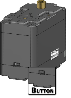
Yes, there is a button at the center rear of the servo (opposite the LED). If you did not press that before, then the stock servo is in serial mode, and you would not have been able to flash new firmware.
Can you take a few clear photos of your setup?
I just realized that button, i never touch it before , but i dont know if the seller of this robot had pressed the button, because the arm robot had been assembled when it arrived.
what should i do next?
The factory reset has been done, but the servo still can not be found. i had servo tester arduino and test the servo, but the servo didnot move,
and I monitored the usb-rx led when updating the firmware, is it normal that the led doesn’t light up at all when the update process in progress?

